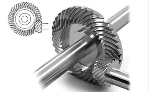
Spiral bevel gears are critical components in applications such as industrial sewing machines, robotics, and precision machinery. This study investigates the meshing characteristics of small-module spiral bevel gears manufactured using the duplex spread blade method under varying loads and misalignment conditions. A systematic workflow combining mathematical modeling, finite element analysis (FEA), and experimental validation is developed to analyze gear performance.
Mathematical Modeling of Duplex Spread Blade Gears
The duplex spread blade method employs dual-sided cutting tools for simultaneous convex and concave tooth surface generation. The cutting edge geometry of the inner and outer blades is defined as:
$$ \mathbf{r}_{0i}(u_i) =
\begin{bmatrix}
\mp(u_i \sin \alpha_{iH} + a_i) \\
0 \\
-(u_i \cos \alpha_{iH} + b_i) \\
1
\end{bmatrix}, \quad i=1,2 $$
where \(a_i = W_i/2 + r_i \cos \alpha_{iH}\) and \(b_i = r_i – r_i \sin \alpha_{iH}\). Coordinate transformation matrices are used to map tool positions to workpiece coordinates during gear generation:
$$ \mathbf{M}_{m0}(\phi_{c1}, \beta_p) = \mathbf{M}_{mc}(\phi_{c1}) \mathbf{M}_{c0}(\beta_p) $$
| Parameter | Pinion | Gear |
|---|---|---|
| Number of teeth | 10 | 39 |
| Module (mm) | 0.9 | 0.9 |
| Spiral angle (°) | 35 | 35 |

Loaded Tooth Contact Analysis
A finite element model was developed using ABAQUS to simulate gear meshing under load. Key results include:
$$ \text{Transmission Error (TE)} = \phi_{\text{output}} – \frac{z_1}{z_2} \phi_{\text{input}} $$
| Load (N·m) | Max Root Stress (MPa) | Max Contact Stress (MPa) |
|---|---|---|
| 1 | 29.2 | 501.1 |
| 3 | 80.7 | 853.7 |
| 5 | 128.6 | 1146.2 |
Effects of Misalignments
Three types of misalignments were analyzed:
- Pinion axial displacement (ΔXp): Causes contact pattern migration from heel to toe
- Gear axial displacement (ΔXg): Induces edge contact at tooth extremities
- Shaft angle error (ΔΣ): Alters load distribution across the face width
The transmission error variation with pinion misalignment follows:
$$ \Delta \text{TE} = 1.9 \times 10^{-5} \cdot e^{2.3|\Delta X_p|} \quad (R^2 = 0.96) $$
| Misalignment | Max Root Stress (MPa) | Max Contact Stress (MPa) |
|---|---|---|
| ΔXp = +0.2 mm | 123.9 | 3626.8 |
| ΔXg = -0.2 mm | 114.6 | 1757.8 |
| ΔΣ = +0.2° | 108.3 | 1088.3 |
Key Findings
- Contact pattern area increases by 42% when load doubles from 3 N·m to 5 N·m
- Positive pinion misalignment increases contact stress by 325% compared to aligned condition
- Shaft angle errors ≤0.2° cause ≤12% variation in transmission error amplitude
The developed methodology enables precise prediction of spiral bevel gear performance under realistic operating conditions, providing critical insights for high-precision gear design and manufacturing.
