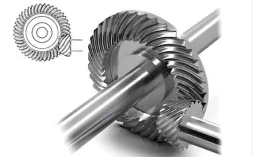
Spiral bevel gears are critical components in power transmission systems due to their high load capacity, smooth operation, and efficiency. This study investigates the sensitivity of machine tool geometric errors to tooth surface deviations through advanced analytical methods. A comprehensive framework is presented to quantify the relationship between 30 geometric error parameters and gear quality metrics.

1. Mathematical Modeling of Tooth Surface Deviation
The ideal tooth surface equation for spiral bevel gears is derived from multi-axis motion transformation:
$$r_g = M_A \cdot M_B \cdot M_Z \cdot M_X \cdot M_Y \cdot r_t(u,\theta)$$
Considering geometric errors, the actual surface becomes:
$$r_g^e = M_A \cdot M_A^e \cdot M_B \cdot M_B^e \cdot M_Z \cdot M_Z^e \cdot M_X \cdot M_X^e \cdot M_Y \cdot M_Y^e \cdot r_t(u,\theta)$$
2. Geometric Error Classification
Five-axis CNC gear milling machines exhibit 30 geometric errors categorized as:
| Error Type | Notation | Quantity |
|---|---|---|
| Linear Errors | δ (x,y,z) | 15 |
| Angular Errors | ε (α,β,γ) | 15 |
3. Sensitivity Analysis Methods
3.1 Local Sensitivity Analysis
The partial derivative approach evaluates parameter influence:
$$S_i^L = \frac{\partial K}{\partial x_i} \cdot \frac{x_i}{K}$$
where $K$ represents total surface deviation:
$$K = \sum_{f=1}^{135} |r_g^e(f) – r_g(f)|$$
3.2 Sobol Global Sensitivity Analysis
Variance decomposition identifies parameter interactions:
$$S_i^T = \frac{\mathbb{E}_{\sim x_i}[Var(K|x_i)]}{Var(K)}$$
Monte Carlo sampling generates input matrices $E$ and $F$ for error propagation analysis.
4. Case Study: Spiral Bevel Gear Parameters
| Parameter | Value |
|---|---|
| Teeth Number | 18 |
| Module (mm) | 4.29 |
| Face Width (mm) | 45 |
| Spiral Angle (°) | 35 |
5. Sensitivity Analysis Results
5.1 Local Sensitivity Ranking
Top 5 influential parameters:
$$S_{17}^L (ε_{βX}) > S_{23}^L (ε_{γZ}) > S_{5}^L (δ_{yY}) > S_{19}^L (ε_{αY}) > S_{14}^L (δ_{yB})$$
5.2 Global Sensitivity Results
First-order indices for critical parameters:
| Parameter | $S_i$ | $S_i^T$ |
|---|---|---|
| ε_{βX} | 0.182 | 0.254 |
| δ_{yY} | 0.154 | 0.201 |
| ε_{γZ} | 0.137 | 0.189 |
6. Error Compensation Strategy
For spiral bevel gear manufacturing, priority should be given to compensating:
$$min \sum_{i=1}^{30} w_i|Δx_i| \quad s.t. \quad K \leq 15μm$$
where weights $w_i$ correspond to sensitivity indices.
7. Method Selection Guidelines
| Criterion | Local SA | Global SA |
|---|---|---|
| Parameter Range | Uniform | Arbitrary |
| Nonlinearity | Weak | Strong |
| Computation Cost | Low | High |
8. Conclusion
This systematic analysis reveals that angular errors about the X-axis (ε_{βX}) and Y-direction linear errors (δ_{yY}) contribute over 35% of total spiral bevel gear surface deviations. The proposed framework enables precision manufacturing through targeted error compensation and machine tool accuracy allocation.
