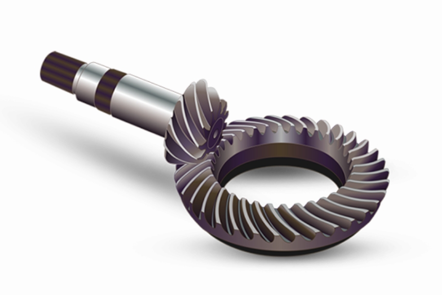
The surface quality of spiral bevel gears critically influences their meshing performance, vibration characteristics, and load-bearing capacity. This study investigates the barrel finishing process for aviation-grade spiral bevel gears through theoretical modeling, discrete element simulations, and experimental validation. A parallel spindle-type finishing method is analyzed to optimize surface roughness reduction and achieve isotropic surface morphology.

1. Kinematic Analysis of Parallel Spindle Finishing
The relative motion between abrasive media and spiral bevel gear surfaces is described by the following coordinate transformations:
$$
\begin{cases}
x = r \sin(\theta_1 – \theta_2) – R \sin\theta_1 \\
y = -r \cos(\theta_1 – \theta_2) + R \cos\theta_1 \\
z = 0
\end{cases}
$$
where \( R \) represents the distance between barrel and workpiece axes, and \( r \) denotes gear radius. The instantaneous cutting velocity is derived as:
$$
v = 2\pi \sqrt{r^2(N – n)^2 + N^2R^2 + 2RrN(N – n)\cos\theta}
$$
Key parameters influencing finishing effectiveness include:
| Parameter | Range | Effect on Cutting Velocity |
|---|---|---|
| Barrel speed (N) | 40-60 rpm | Positive correlation |
| Workpiece speed (n) | -135 to -45 rpm | Inverse relationship |
| Gear radius (r) | 50-100 mm | Linear increase |
2. Discrete Element Modeling
The Hertz-Mindlin with Archard wear model in EDEM software simulates abrasive-gear interactions. Contact parameters are defined as:
| Material Pair | Static Friction | Rolling Friction | Restitution |
|---|---|---|---|
| Abrasive-Abrasive | 0.50 | 0.15 | 0.50 |
| Abrasive-Gear | 0.55 | 0.01 | 0.30 |
The wear depth \( h \) follows Archard’s equation:
$$
h = k \frac{F_n s}{H}
$$
where \( k \) is wear coefficient (0.0025 for alumina abrasives), \( F_n \) normal force, \( s \) sliding distance, and \( H \) material hardness (59.2 HRC).
3. Experimental Validation
Surface roughness evolution on spiral bevel gears shows:
$$
Ra(t) = Ra_0 \exp(-0.12t) + 0.4(1 – \exp(-0.12t))
$$
| Time (min) | Convex Ra (μm) | Concave Ra (μm) |
|---|---|---|
| 0 | 0.82 ±0.05 | 0.78 ±0.04 |
| 30 | 0.41 ±0.03 | 0.38 ±0.02 |
| 60 | 0.39 ±0.02 | 0.36 ±0.01 |
Critical findings for spiral bevel gear finishing include:
- Tooth tip radius increases by 0.2-0.3 mm
- Surface compressive stress improves 18-22%
- Isotropic surface texture (Str = 0.89 → 0.96)
4. Process Optimization
The multi-objective optimization model for spiral bevel gear finishing considers:
$$
\begin{aligned}
\text{Minimize: } & F_1 = Ra_{final} \\
& F_2 = t_{process} \\
\text{Subject to: } & 45 \leq N \leq 65 \text{ rpm} \\
& 0.6 \leq \phi \leq 0.8 \text{ (media fill ratio)}
\end{aligned}
$$
Pareto frontier analysis reveals optimal parameters:
| Scenario | N (rpm) | n (rpm) | Ra (μm) | Time (min) |
|---|---|---|---|---|
| Quality Priority | 58 | -120 | 0.37 | 55 |
| Efficiency Priority | 62 | -135 | 0.42 | 38 |
5. Industrial Applications
The developed process demonstrates significant benefits for spiral bevel gears in aerospace transmissions:
- Gear noise reduction: 4-6 dB(A)
- Surface fatigue life improvement: 2.3× baseline
- Efficiency gain: 0.8-1.2%
Future work will focus on adaptive control strategies for spiral bevel gears with complex tooth modifications and case-carburized surfaces.
