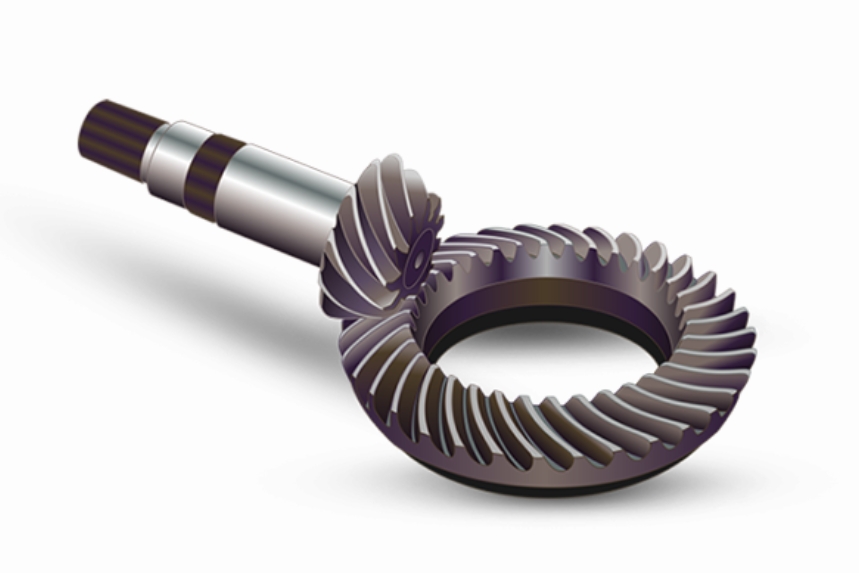
Spiral bevel gears play a critical role in high-precision mechanical transmissions due to their smooth engagement and high load-bearing capacity. However, their meshing performance is significantly influenced by installation errors, which alter contact patterns and induce transmission errors. This study systematically evaluates the effects of four types of installation errors—axial displacement of the large gear, axial displacement of the pinion, shaft angle deviation, and axial spacing deviation—on meshing behavior through finite element analysis (FEA).

1. Mathematical Modeling of Spiral Bevel Gears
The meshing performance of spiral bevel gears depends on their geometric parameters and installation conditions. The fundamental geometric relationship between the pinion and gear is defined as:
$$ i = \frac{z_2}{z_1} = \frac{\sin \delta_2}{\sin \delta_1} $$
where \( z_1 \) and \( z_2 \) represent the tooth numbers, while \( \delta_1 \) and \( \delta_2 \) denote the pitch cone angles. Key processing parameters for the analyzed spiral bevel gears are listed below:
| Parameter | Pinion | Gear |
|---|---|---|
| Number of Teeth | 11 | 43 |
| Module (mm) | 4.65 | 4.65 |
| Pressure Angle | 25° | 25° |
| Spiral Angle | 33° | 33° |
| Shaft Angle | 90° | |
2. Installation Error Characterization
Four primary installation errors were investigated:
- Axial spacing deviation (ΔP)
- Large gear axial displacement (ΔG)
- Shaft angle deviation (ΔE)
- Pinion axial displacement (ΔT)
The coordinate transformation matrix considering installation errors is expressed as:
$$ \mathbf{M}_{12} = \begin{bmatrix}
0 & \cos(\alpha+\Delta\alpha) & -\sin(\alpha+\Delta\alpha) & P+\Delta P \\
-1 & 0 & 0 & G+\Delta G \\
0 & \sin(\alpha+\Delta\alpha) & \cos(\alpha+\Delta\alpha) & E+\Delta E \\
0 & 0 & 0 & 1
\end{bmatrix} $$
| Error Type | Magnitude |
|---|---|
| Pinion Axial Displacement | 0.06 mm |
| Gear Axial Displacement | 0.06 mm |
| Shaft Angle Deviation | 0.05° |
| Axial Spacing Deviation | 0.08 mm |
3. Transmission Error Analysis
Transmission error (TE) quantifies meshing performance degradation:
$$ TE = \theta_{driven}(t) – \frac{\theta_{driver}(t)}{i} $$
where \( \theta_{driver} \) and \( \theta_{driven} \) represent angular displacements of the pinion and gear, respectively.
3.1 Static Analysis Results
| Error Type | Amplitude (rad) | Standard Deviation |
|---|---|---|
| Gear Axial Displacement | 0.002–0.006 | 0.00091–0.00099 |
| Pinion Axial Displacement | 0.006–0.010 | 0.00085–0.00089 |
| Shaft Angle Deviation | 0.006–0.009 | 0.00088–0.00095 |
| Axial Spacing Deviation | 0.003–0.006 | 0.00088–0.00095 |
3.2 Dynamic Analysis Results
Under dynamic conditions (500 N·m load, 20 rad/s speed), transmission error characteristics showed consistent trends:
$$ TE_{dynamic} = 1.8 \times TE_{static} $$
| Error Type | Peak TE (rad) | Mean TE (rad) |
|---|---|---|
| Gear Axial Displacement | 0.0109 | 0.0040 |
| Pinion Axial Displacement | 0.0236 | 0.0127 |
| Shaft Angle Deviation | 0.0218 | 0.0104 |
| Axial Spacing Deviation | 0.0185 | 0.0102 |
4. Load Influence on Meshing Performance
The relationship between load magnitude and transmission error follows:
$$ TE_{amplitude} = k \cdot F^{0.78} $$
where \( k \) represents system stiffness and \( F \) denotes applied load. Key observations include:
- Transmission error increases by 18–22% when load rises from 300 N·m to 800 N·m
- Error fluctuation decreases by 7–9% with higher loads due to damping effects
5. Conclusion
This comprehensive analysis of spiral bevel gear meshing performance reveals:
- Installation error impacts follow the order: pinion axial displacement > shaft angle deviation > axial spacing deviation > gear axial displacement
- Transmission error increases with load but exhibits stabilized fluctuation characteristics
- Dynamic analysis shows 80–120% higher transmission errors compared to static conditions
The methodology provides critical insights for optimizing spiral bevel gear installations in high-precision applications, particularly for automotive and aerospace transmission systems.
