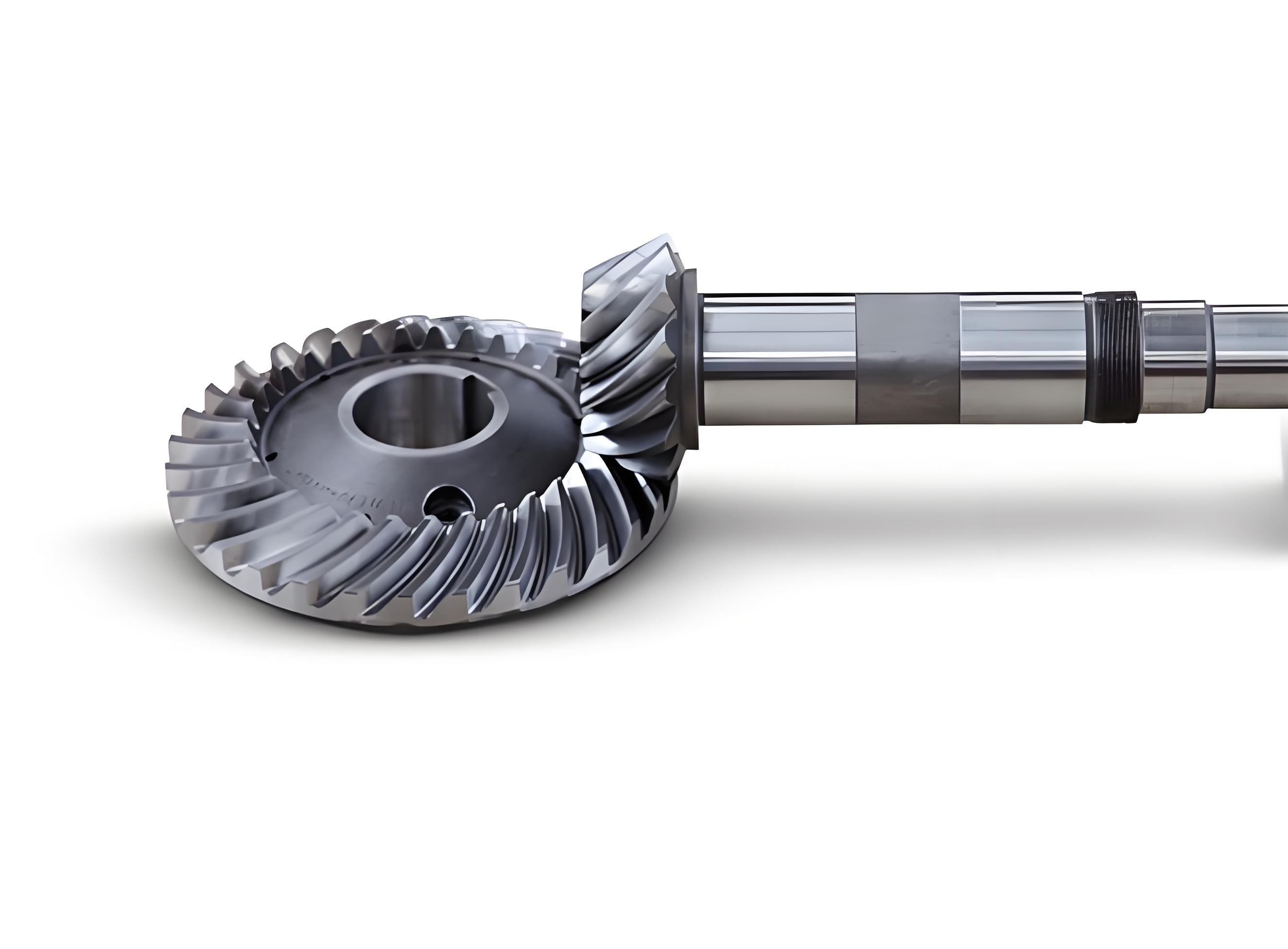
This study presents an active design and manufacturing methodology for face-milled spiral bevel gears using free-form surface machine tools. By establishing a mathematical model for gear meshing and machining kinematics, the proposed approach enables precise control over contact properties while eliminating errors caused by workpiece axis motion inaccuracies.

1. Gear Pair Meshing Model
The contact properties of spiral bevel gear pairs are governed by four critical parameters:
- Position coordinates of average contact point $({\bar{h}}_{Ref}, {\bar{v}}_{Ref})$
- Contact path orientation angle $\theta$
- Major axis length $L$ of instantaneous contact ellipse
- Transmission error function $TE(\phi_P)$
The transmission error is defined as:
$$TE = \phi_W – \phi^*_W = c_2(\phi_P – \phi^P_{Ref})^2$$
where $c_2$ represents the quadratic coefficient calculated by:
$$c_2 = \frac{TE_{\text{max}}}{(\pi/Z_P)^2}$$
| Parameter | Pinion | Gear |
|---|---|---|
| Shaft angle (°) | 90.000 | |
| Spiral direction | Left | Right |
| Number of teeth | 7 | 39 |
| Mean spiral angle (°) | 43.850 | 35.833 |
2. Tooth Surface Design Based on Contact Properties
The mathematical model for gear meshing satisfies:
$$\mathbf{v}^{WP}_M \cdot \mathbf{n}^W_M = 0$$
where $\mathbf{v}^{WP}_M$ represents relative velocity vector and $\mathbf{n}^W_M$ denotes unit normal vector.
The coordinate transformation matrices between gear and pinion coordinate systems are defined as:
Pinion coordinate transformation:
$$\mathbf{M}_{PP_d} = \begin{bmatrix}
1 & 0 & 0 & 0 \\
0 & \cos\phi_P & \sin\phi_P & 0 \\
0 & -\sin\phi_P & \cos\phi_P & 0 \\
0 & 0 & 0 & 1
\end{bmatrix}$$
| Parameter | Outer Blade | Inner Blade |
|---|---|---|
| Blade angle (°) | -22.500 | 22.500 |
| Fillet radius (mm) | 2.290 | |
| Tool radius (mm) | 152.400 | – |
3. Workpiece-Fixed Machining Methodology
The constraint equations for pinion machining are established as:
$$\begin{cases}
\mathbf{r}^P_M = \mathbf{r}^c_M \\
\mathbf{n}^P_M = \mathbf{n}^c_M \\
\mathbf{r}^{Pf}_M = \mathbf{r}^{cb}_M \\
\mathbf{n}^{Pf}_M \cdot \mathbf{t}^{cb}_M = 0
\end{cases}$$
The tool center coordinates are determined through quintic polynomial fitting:
$$\begin{cases}
X_{Oc} = \sum_{i=0}^5 c_{xi}\phi_P^i \\
Y_{Oc} = \sum_{i=0}^5 c_{yi}\phi_P^i \\
Z_{Oc} = \sum_{i=0}^5 c_{zi}\phi_P^i
\end{cases}$$
| Axis | Constant | 1st Order | 2nd Order |
|---|---|---|---|
| XOc (mm) | -101.82 | 17.95 | 1.97 |
| YOc (mm) | 8.87 | 2.17 | -0.12 |
4. Numerical Verification and Experimental Validation
The tooth contact analysis (TCA) results demonstrate excellent agreement with design targets:
| Parameter | Drive Side | Coast Side |
|---|---|---|
| Contact path angle (°) | 23.000 | -28.451 |
| Ellipse major axis (mm) | 10.000 | 7.658 |
| TEmax (μrad) | 90.000 | 99.822 |
The rolling test results confirm that the actual contact patterns match the TCA predictions within 5% deviation, validating the effectiveness of the proposed methodology for spiral bevel gear manufacturing.
5. Conclusion
The developed active design methodology enables precise control over spiral bevel gear contact characteristics through:
- Parametric modeling of meshing performance
- Advanced tooth surface modification algorithms
- Workpiece-fixed machining strategy
- Integrated TCA and manufacturing verification
This approach significantly improves the manufacturing accuracy of spiral bevel gears while reducing sensitivity to machine tool motion errors, providing an effective solution for high-performance gear production in aerospace and automotive applications.
