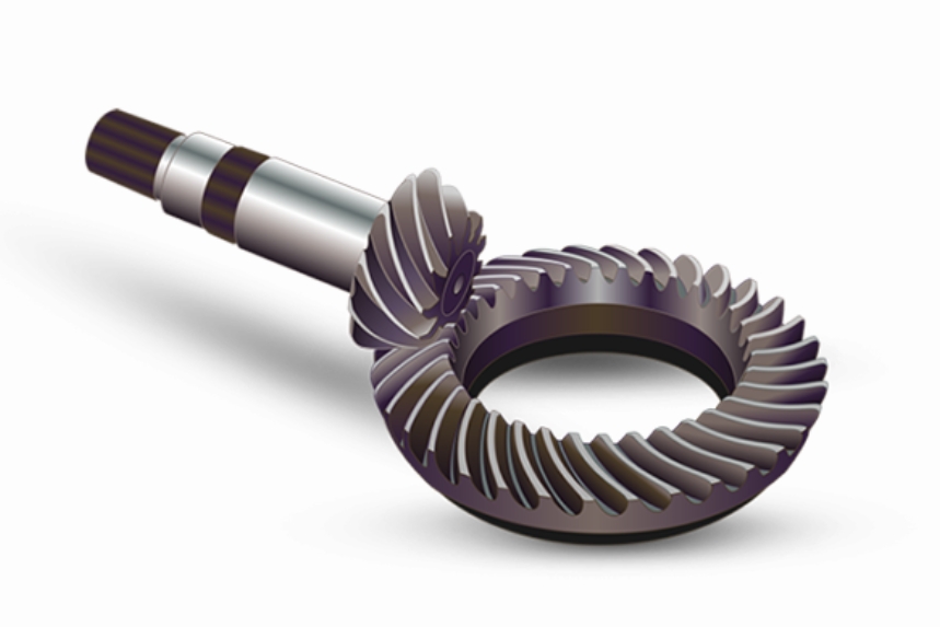
Spiral bevel gears made of 20Cr2Ni4 alloy steel are critical components in heavy-duty machinery due to their superior load-bearing capacity and fatigue resistance. However, grinding-induced thermal damage remains a persistent challenge during post-carburizing finishing. This study systematically investigates the grinding burn characteristics and cracking mechanisms in spiral bevel gears through microstructural analysis and hardness profiling.

Material Characteristics and Heat Treatment
The chemical composition of 20Cr2Ni4 steel is critical for understanding its response to grinding operations. Table 1 compares the measured composition with standard specifications.
| Element | C | Si | Mn | Cr | Ni | P | S |
|---|---|---|---|---|---|---|---|
| Measured | 0.249 | 0.291 | 0.554 | 1.652 | 4.149 | 0.016 | 0.011 |
| Standard | 0.17-0.23 | 0.17-0.37 | 0.30-0.60 | 1.25-1.65 | 3.25-3.65 | <0.030 | <0.030 |
The carburizing process follows the thermal profile:
$$ T(t) = T_{carb} – \beta e^{-\alpha t} $$
Where \( T_{carb} \) = 930°C (carburizing temperature), \( \alpha \) = 0.15 min⁻¹ (thermal decay constant), and \( \beta \) = 120°C (temperature gradient coefficient).
Grinding Burn Formation Mechanism
The grinding energy partition model explains heat generation during spiral bevel gear finishing:
$$ q = \frac{F_t v_s}{l_c b} $$
Where \( q \) = heat flux (W/mm²), \( F_t \) = tangential force (N), \( v_s \) = wheel speed (m/s), \( l_c \) = contact length (mm), and \( b \) = width of cut (mm).
| Location | Surface Hardness (HV) | Effective Case Depth (mm) | Burn Depth (mm) |
|---|---|---|---|
| Uncracked Pitch Circle | 668.6 | 2.386 | 0 |
| Cracked Tooth Root | 477.9 | 1.300 | 0.900 |
| Crack Zone | 820.0 | N/A | 0.300 (White Layer) |
Microstructural Evolution
The phase transformation during grinding can be modeled using the Koistinen-Marburger equation:
$$ f_M = 1 – \exp[-k(M_s – T_q)] $$
Where \( f_M \) = martensite fraction, \( k \) = kinetic coefficient (0.011°C⁻¹), \( M_s \) = martensite start temperature, and \( T_q \) = quenching rate.
Preventive Measures for Spiral Bevel Gears
The critical grinding parameters for spiral bevel gears should satisfy:
$$ \frac{v_w}{v_s} \sqrt{a_e} \leq C_{thermal} $$
Where \( v_w \) = workpiece speed (m/min), \( a_e \) = radial engagement (mm), and \( C_{thermal} \) = material-specific thermal constant (0.25 for 20Cr2Ni4).
Process Optimization Strategy
For spiral bevel gear grinding, the optimized parameters should maintain specific energy below:
$$ e_c = \frac{P}{Q_w} \leq 45 \, \text{J/mm³} $$
Where \( P \) = grinding power (W) and \( Q_w \) = material removal rate (mm³/s).
Conclusion
This investigation reveals that spiral bevel gear failures primarily result from improper grinding parameter selection rather than material deficiencies. The crescent-shaped grinding burns observed in 20Cr2Ni4 spiral bevel gears demonstrate the critical need for thermal management during finishing operations. Implementation of CBN wheels with optimized coolant strategies effectively reduces grinding zone temperatures below the critical Ac1 transformation point, ensuring superior surface integrity for heavy-duty spiral bevel gear applications.
