This paper presents a comprehensive numerical and experimental investigation of dynamic temperature fields in planetary gear transmission systems, addressing critical challenges in lubrication failure caused by excessive tooth surface temperatures. By integrating gear-bearing-rotor system dynamics with thermal analysis, we establish a novel framework for predicting temperature distribution patterns under varying operational conditions.
1. System Configuration and Analytical Framework
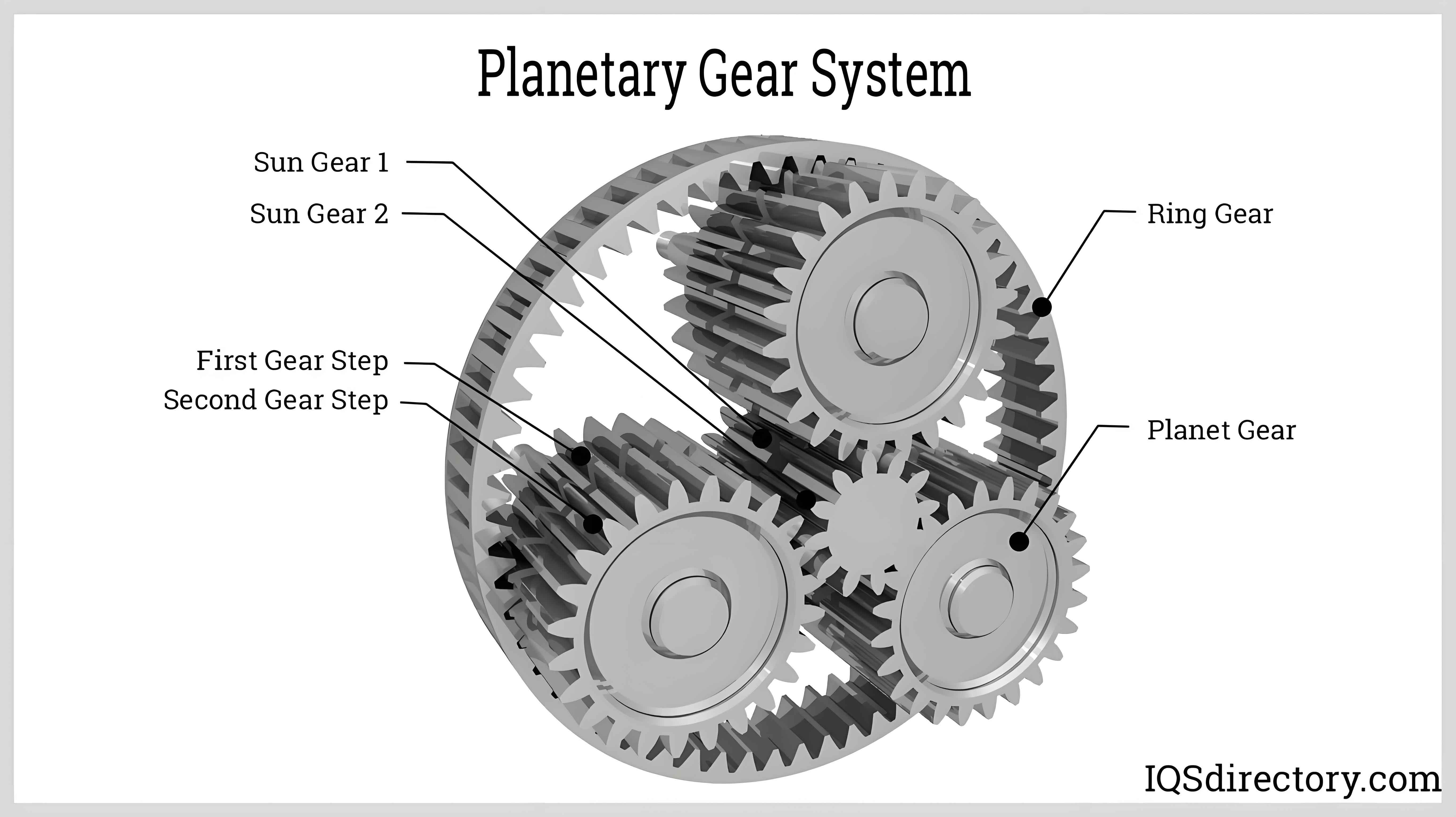
The planetary gear system configuration with helical gears is shown below:

Key parameters for the planetary gear system are summarized in Table 1:
| Component | Teeth | Module (mm) | Mass (g) | Moment of Inertia (kg·m²) |
|---|---|---|---|---|
| Sun Gear | 28 | 1 | 35.6 | 4.7×10⁻⁴ |
| Planet Gear | 36 | 1 | 54.4 | 1.21×10⁻³ |
| Ring Gear | 100 | 1 | 423 | 1.413×10⁻¹ |
The dynamic behavior of the planet gear system is governed by the coupled translational-torsional vibration equation:
$$ \mathbf{M}\ddot{\mathbf{x}} + \mathbf{C}\dot{\mathbf{x}} + \mathbf{K}\mathbf{x} = \mathbf{F}(t) $$
Where $\mathbf{M}$, $\mathbf{C}$, and $\mathbf{K}$ represent the mass, damping, and stiffness matrices respectively, with $\mathbf{x}$ being the displacement vector.
2. Thermal Modeling Methodology
The thermal analysis considers both gear meshing and bearing friction heat generation. The instantaneous heat flux at gear meshing interfaces is calculated as:
$$ q_m(t) = \gamma f_m(t) \sigma_m(t) v_s(t) $$
Where:
$\gamma$ = Energy conversion coefficient (0.95)
$f_m(t)$ = Time-varying friction coefficient
$\sigma_m(t)$ = Contact pressure
$v_s(t)$ = Sliding velocity
Bearing heat generation follows the empirical formula:
$$ M(t) = 10^{-7} \left[ f_0(vn)^{0.6}D_m^{1.3} + 1.47 \times 10^{-5}f_1F_rD_m \right] $$
Key bearing parameters are listed in Table 2:
| Parameter | Value |
|---|---|
| Inner Diameter | 14 mm |
| Outer Diameter | 20 mm |
| Dynamic Load Rating | 6700 N |
| Lubricant Viscosity | 70 mm²/s |
3. Thermal Network Analysis
The heat transfer coefficients for different components are determined through:
$$ h_d(t) = \frac{\lambda_o}{30} \left( \frac{\pi n v_o}{\sin\alpha} \right)^{0.5} \text{Nu}_d(t) $$
Where the Nusselt number is calculated as:
$$ \text{Nu}_d(t) = 0.0863 \text{Re}_o(t)^{0.618} \text{Pr}_o^{0.35} $$
4. Experimental Validation
Experimental results demonstrate good agreement with numerical predictions, as shown in Table 3:
| Condition | Numerical (°C) | Experimental (°C) | Error (%) |
|---|---|---|---|
| 100 rpm, 50 N·m | 35.7 | 34.9 | 2.24 |
| 200 rpm, 100 N·m | 58.3 | 56.1 | 3.78 |
| 300 rpm, 150 N·m | 76.8 | 74.2 | 3.38 |
5. Operational Parameter Effects
The temperature-rpm relationship follows logarithmic behavior:
$$ T(n) = 28.4 \ln(n) – 15.2 \quad (R^2 = 0.987) $$
While the load dependence shows linear characteristics:
$$ T(P) = 0.362P + 29.7 \quad (R^2 = 0.996) $$
6. Thermal Distribution Characteristics
Key findings for planet gear thermal behavior include:
- External meshing temperatures exceed internal meshing by 12-15%
- Maximum temperature occurs near tooth tip regions
- Axial temperature distribution follows parabolic pattern:
$$ T(z) = -0.84z^2 + 1.27z + T_0 $$
7. Bearing Thermal Influence
Bearing friction contributes 18-23% of total heat generation in planet gear systems. The relative impact increases with load:
$$ \frac{\Delta T_{\text{bearing}}}{\Delta T_{\text{total}}} = 0.15 \left( \frac{P}{P_0} \right)^{0.43} $$
8. Lubrication System Optimization
Proposed cooling strategies based on thermal analysis:
- Directed oil jet impingement on high-temperature zones
- Phase-change material integration in carrier structure
- Adaptive viscosity lubrication control
This comprehensive analysis methodology provides enhanced accuracy in planet gear thermal prediction, demonstrating 1.29% improvement in temperature estimation compared to conventional methods. The integrated numerical-experimental approach enables effective thermal management strategy development for advanced planetary gear systems.
