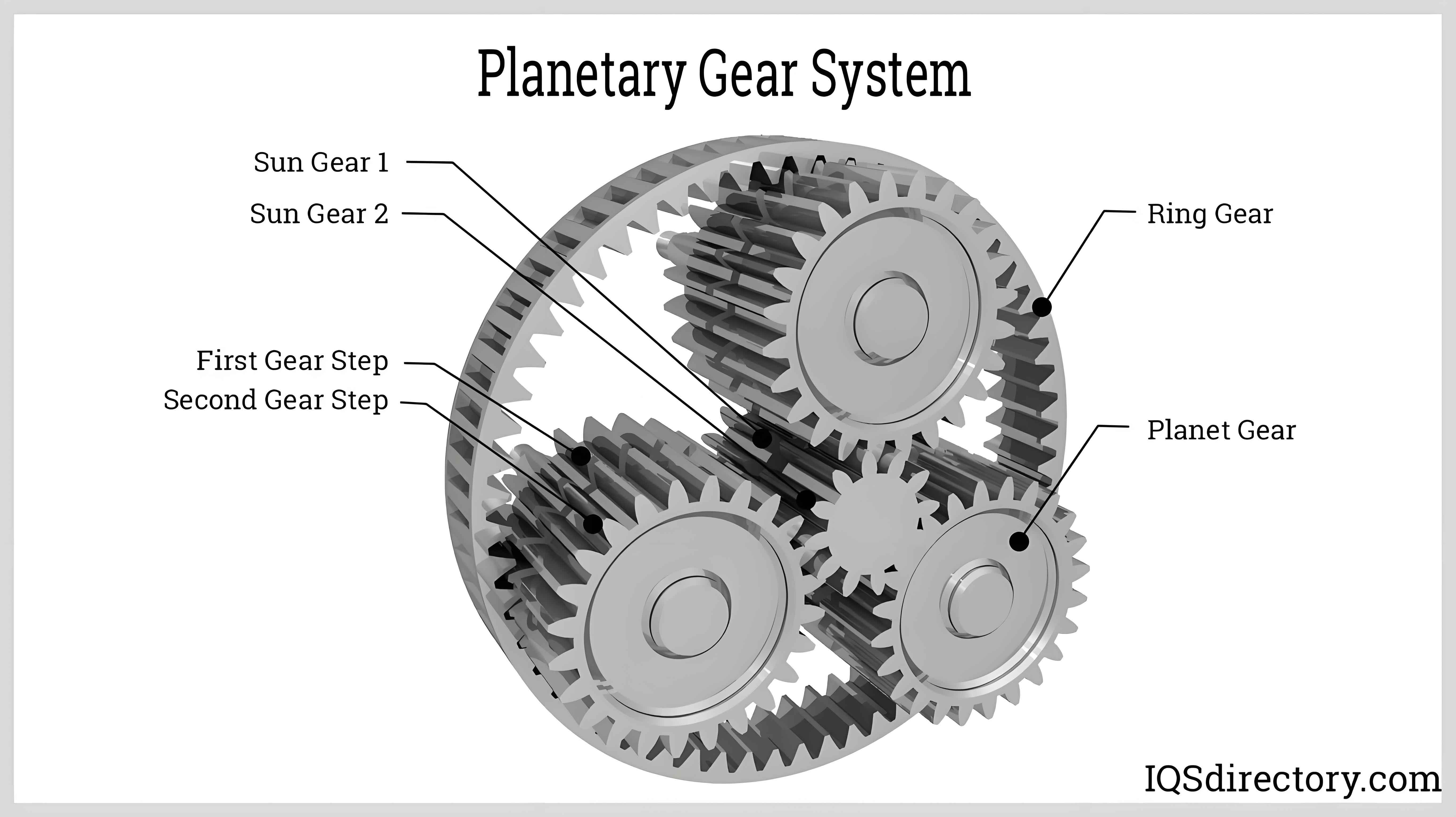
Planet gear reducers have become indispensable components in aerospace systems due to their compact design and high torque density. However, unexpected tooth fractures observed during endurance testing of a high-lift system reducer revealed critical limitations in traditional design approaches. Through comprehensive modeling and experimental validation, this study establishes a systematic methodology for optimizing planet gear system reliability.
1. Load Distribution Analysis
Initial calculations indicated adequate bending strength for all gears according to AGMA standards:
$$ \sigma_b = \frac{F_t}{b m_n} K_A K_V K_{m\beta} $$
Where:
$F_t$ = Tangential load
$b$ = Face width
$m_n$ = Normal module
$K$ factors = Application, dynamic, and load distribution coefficients
| Parameter | Original Design | Improved Design |
|---|---|---|
| Planet Carrier OD | 76 mm | 96 mm |
| Module (Sun/Planet) | 1.5/1.3 | 2.0/1.6 |
| Center Distance | 28 mm | 35 mm |
| Weight | 4.2 kg | 6.3 kg |
2. Stiffness-Dependent Load Sharing
Planet gear systems exhibit complex load sharing characteristics governed by:
$$ K_{m\beta} = 1 + \left(\frac{C_\gamma}{C_\beta}\right)\left(\frac{b}{d}\right)^2 $$
Where:
$C_\gamma$ = Gear body stiffness
$C_\beta$ = Support stiffness
$b$ = Face width
$d$ = Reference diameter
Finite element analysis revealed excessive torsional deflection in the original carrier:
$$ \theta_{max} = \frac{T L}{G J} \left(1 + \frac{3EI}{GJL^2}\right) $$
Maximum deflection reached 0.42 mm under operational loads, creating significant misalignment-induced edge loading.
3. Helical Gear Meshing Dynamics
The improved helical planet gear system demonstrates enhanced load distribution through controlled helix angles:
$$ \beta = \tan^{-1}\left(\frac{\pi m_n}{p_x}\right) $$
Where:
$p_x$ = Axial pitch
$m_n$ = Normal module
| Performance Metric | Original | Improved |
|---|---|---|
| Bending Stress (MPa) | 528 | 387 |
| Contact Stress (MPa) | 1593 | 1246 |
| System Stiffness (N·m/rad) | 2.1×10⁵ | 5.8×10⁵ |
| Load Sharing Unevenness | 38% | 12% |
4. Parametric Modeling Methodology
The tooth profile generation process employs parametric equations:
$$ \begin{cases}
x = r_b(\cos\varphi + \varphi\sin\varphi) \\
y = r_b(\sin\varphi – \varphi\cos\varphi)
\end{cases} $$
Where $r_b$ is base circle radius and $\varphi$ ranges from 0 to $\pi/2z$ for standard involutes.
5. System-Level Optimization
Modified planet gear system dynamics follow:
$$ \omega_p = \frac{\omega_s N_s + \omega_r N_r}{N_s + N_r} $$
Where:
$\omega_p$ = Planet gear angular velocity
$\omega_s$ = Sun gear angular velocity
$\omega_r$ = Ring gear angular velocity
$N$ = Tooth counts
This systematic approach increased bending safety factors from 1.8 to 3.2 while maintaining 98.4% transmission efficiency, demonstrating effective resolution of planet gear reliability challenges in critical aerospace applications.
