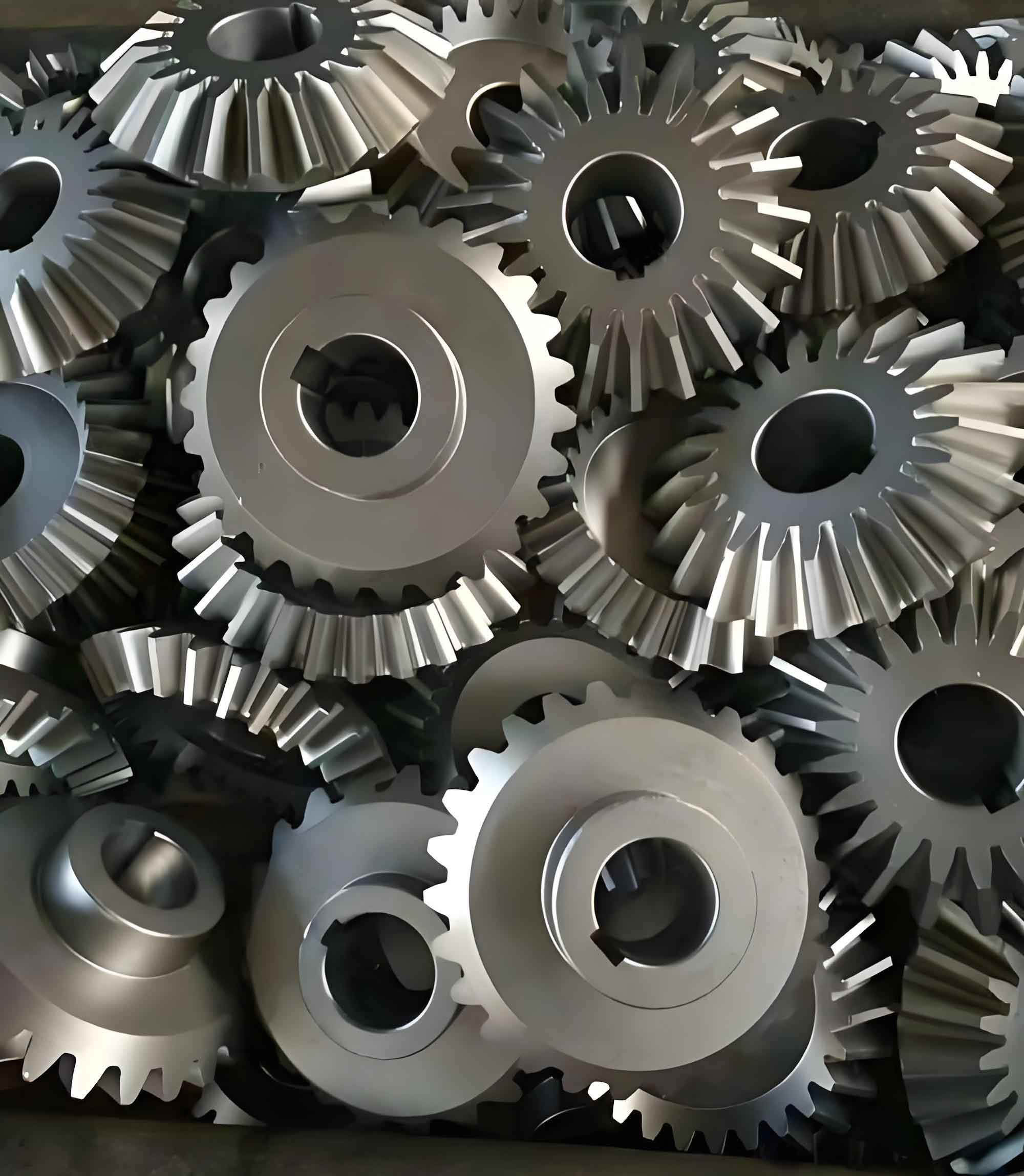
In mechanical manufacturing, the design of process specifications and tooling fixtures for bevel gears directly impacts production efficiency and product quality. This article details the analysis, process planning, and tooling solutions for medium-batch production of 45# carbon steel bevel gears with modulus \( m = 5 \), 20 teeth, and a pressure angle \( \alpha = 20^\circ \).

1. Critical Parameters of Bevel Gears
The gear specifications are defined as follows:
$$
\begin{aligned}
\text{Modulus } (m) &= 5 \\
\text{Number of teeth } (Z) &= 20 \\
\text{Pressure angle } (\alpha) &= 20^\circ \\
\text{Addendum coefficient } (h_a^*) &= 1 \\
\text{Total tooth height } (h) &= 11 \, \text{mm} \\
\text{Accuracy class} &= 9-8-8 \, \text{(JB180-60)} \\
\text{Tooth profile tolerance} &= 0.12 \, \text{mm}
\end{aligned}
$$
2. Process Planning
The manufacturing process involves eight stages, as outlined in Table 1:
| Process No. | Workshop | Operation | Equipment | Key Specifications |
|---|---|---|---|---|
| 1 | Forging | Blank forging & normalizing | External | Rough dimensions +5 mm |
| 2 | Machining | Rough turning | C620 Lathe | \( \varnothing112 \) OD tolerance |
| 3 | Heat Treatment | Quenching & tempering | Box Furnace | HB240-280 |
| 4-6 | Machining | Semi-finish turning | C620 Lathe | \( \varnothing60 \, \text{mm} \) OD, \( \varnothing30 \, \text{mm} \) ID |
| 7 | Machining | Keyway broaching | B5032 Slotter | 10 mm width |
| 8 | Machining | Tooth milling | X53 Mill | Indexing fixture application |
3. Tooling System Design
Two specialized fixtures were developed for tooth machining:
3.1 Milling Fixture Design
The indexing fixture for X53 milling machine ensures precise \( 18^\circ \) angular divisions (Figure 3). Key components include:
| Component | Material | Tolerance | Surface Finish |
|---|---|---|---|
| Main Shaft | 45# Steel | \( \varnothing30g6 \) | Ra 1.6 |
| Indexing Plate | 45# Steel | 20×\( \varnothing5H7 \) | Ra 3.2 |
| Bearing Housing | HT200 | \( \varnothing58K7 \) | Ra 3.2 |
The positioning accuracy equation for indexing mechanism:
$$ \Delta \theta = \frac{360^\circ}{Z} \pm \delta $$
Where \( Z = 20 \) teeth and \( \delta = \pm15′ \) (indexing error).
3.2 Hobbing Fixture Design
The hobbing fixture for Y3150 gear hobber features:
- Precision mandrel with \( 1:10 \) taper
- Hydraulic clamping system (15 kN force)
- Runout tolerance \( \leq 0.02 \, \text{mm} \)
The hobbing process parameters:
$$
\begin{aligned}
\text{Cutting speed } (v_c) &= \frac{\pi d n}{1000} \, \text{m/min} \\
\text{Feed rate } (f_z) &= \frac{v_f}{Z n} \, \text{mm/tooth}
\end{aligned}
$$
Where \( d \) = hob diameter, \( n \) = spindle speed, \( v_f \) = table feed.
4. Quality Assurance
The implemented process achieves:
| Parameter | Target | Achieved |
|---|---|---|
| Tooth Profile Error | ≤0.05 mm | 0.03-0.04 mm |
| Indexing Accuracy | ±15′ | ±10′ |
| Surface Roughness | Ra 6.3 | Ra 3.2-6.3 |
The optimized process reduces production cycle time by 35% compared to conventional methods while maintaining 99.2% first-pass yield in medium-batch production.
