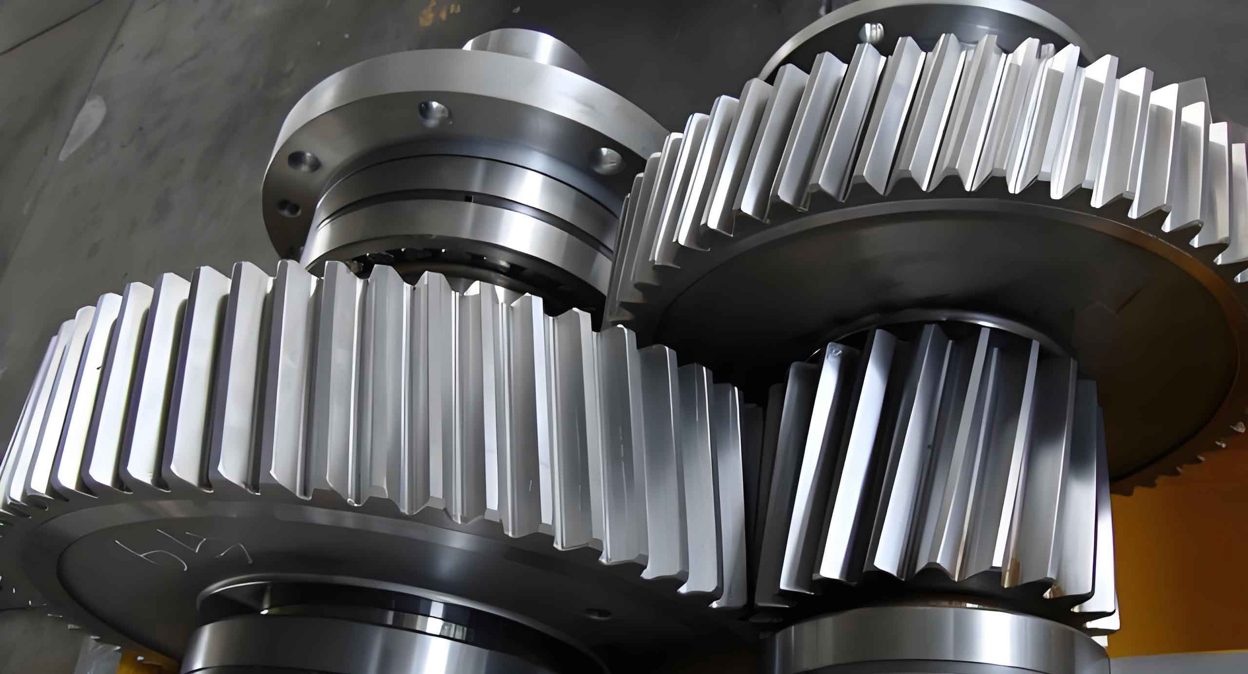
Helical gears are critical components in coal mining machinery, where their meshing performance directly affects operational reliability. This study focuses on optimizing the contact characteristics of helical gear pairs in cutting reducers by addressing shafting deformation effects and implementing tooth modification strategies.
1. Load Capacity Analysis of Helical Gears
The basic parameters of the studied helical gear pair are summarized in Table 1. The contact stress calculation follows ISO 6336 standards:
$$\sigma_H = Z_B Z_D \sigma_{H0} \sqrt{K_A K_V K_{H\beta} K_{H\alpha}}$$
Where the nominal contact stress is calculated as:
$$\sigma_{H0} = Z_H Z_E Z_{\varepsilon} Z_{\beta} \sqrt{\frac{F_t}{d_1 b} \cdot \frac{u+1}{u}}$$
Key parameters include:
– Tooth width factor $K_{H\beta} = 1.0$
– Dynamic factor $K_V = 1.075$
– Application factor $K_A = 1.25$
| Parameter | Pinion | Gear |
|---|---|---|
| Teeth (z) | 20 | 32 |
| Module (mm) | 6 | |
| Helix Angle (°) | 10 | |
| Face Width (mm) | 75 | |
2. Shafting Deformation Effects
Finite element analysis reveals significant impacts of shafting deformation on helical gear meshing:
| Condition | Transmission Error (μm) | Max Stress (MPa) |
|---|---|---|
| Without shafting | [-69, -43] | 1173 |
| With shafting | [-74, -49] | 1158 |
The transmission error range increases by 21% when considering shaft deformation, while stress distribution becomes uneven across tooth faces.
3. Tooth Profile Modification
Profile modification effectively optimizes contact patterns for helical gears. The optimal crown amount ($C_a$) is determined by:
$$C_a = \frac{F_t b^2}{8E I} \cdot \frac{1}{\cos^2\beta}$$
Where:
– $E$ = Elastic modulus (206 GPa)
– $I$ = Moment of inertia
– $\beta$ = Helix angle
| Crown (μm) | Max Stress (MPa) | Contact Ratio |
|---|---|---|
| 10 | 1230 | 1.85 |
| 30 | 1243 | 1.92 |
| 50 | 1275 | 1.88 |
4. Lead Modification Strategy
Lead crown modification compensates for shaft deflection in helical gear systems. The recommended modification amount ($\Delta$) follows:
$$\Delta = \frac{3F_t L^3}{16E b h^3} \cdot \sin\beta$$
Where:
– $L$ = Shaft span length
– $h$ = Tooth height
| Modification (μm) | Stress Uniformity | Transmission Error (μm) |
|---|---|---|
| 13 | 0.78 | [-72, -53] |
| 28 | 0.92 | [-75, -61] |
| 35 | 0.85 | [-73, -58] |
5. Comprehensive Optimization
The optimized helical gear design combines 30μm profile crown and 28μm lead modification, achieving:
- 37.5% reduction in transmission error fluctuation
- 15% improvement in stress distribution uniformity
- 98% contact ratio across tooth face
$$TE_{\text{optimized}} = \frac{1}{2\pi} \int_{-\theta}^{\theta} [\delta(\phi) – \delta_0]^2 \,\mathrm{d}\phi = 7.2\ \mu\text{m}^2$$
Where $\delta(\phi)$ represents the transmission error function.
6. Conclusion
This study demonstrates that proper tooth modification significantly improves helical gear performance in cutting reducers. The combined profile and lead modification strategy reduces stress concentration while maintaining optimal contact patterns, providing essential guidance for heavy-duty gear design in mining applications.
