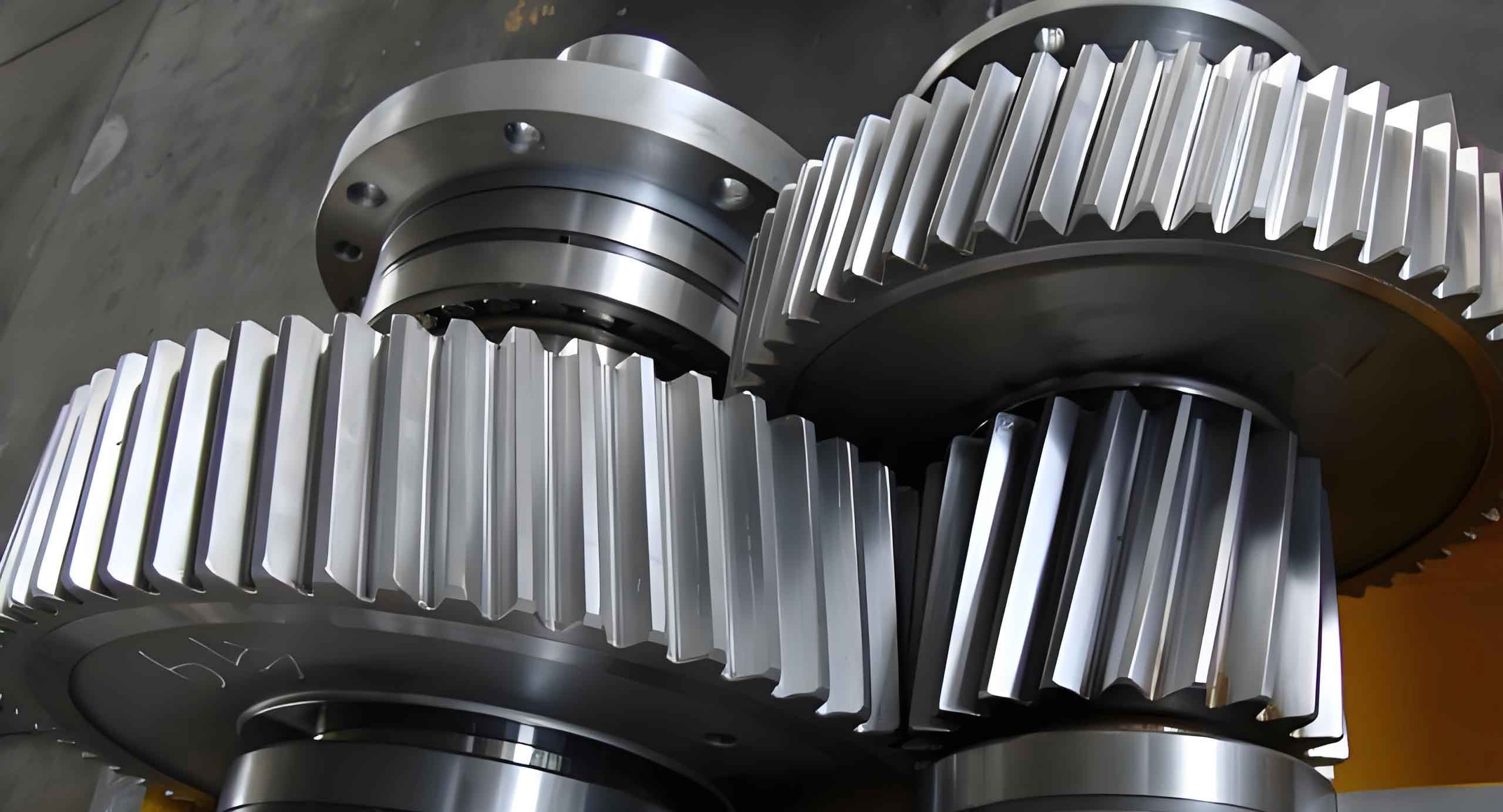
Helical gear systems with double-input and single-output (DI-SO) configurations are critical components in marine propulsion systems. This study investigates the vibration characteristics of such systems under asymmetrical load conditions, focusing on nonlinear instability phenomena caused by unsymmetrical load ratios and magnitudes. A torsional vibration model is established to analyze bifurcation behaviors, time-frequency responses, phase portraits, and Poincaré maps, revealing the dynamic evolution mechanisms.

1. Dynamic Modeling of DI-SO Helical Gear Systems
The dimensionless governing equations for the three-degree-of-freedom system are derived as:
$$
\left\{
\begin{aligned}
u” + 2\xi_{11}u’ + 2\xi_{12}v’ + \kappa_{11}(\tau)g(u) + \kappa_{12}(\tau)g(v) &= f_1 + \bar{e}”_1(\tau) \\
v” + 2\xi_{21}u’ + 2\xi_{22}v’ + \kappa_{21}(\tau)g(u) + \kappa_{22}(\tau)g(v) &= f_2 + \bar{e}”_2(\tau)
\end{aligned}
\right.
$$
where \( g(x) \) represents the nonlinear backlash function approximated by a 7th-order polynomial:
$$
g(x) = 0.0017x^7 – 0.0366x^5 + 0.2833x^3 – 0.1555x
$$
2. Key Parameters of Helical Gear Systems
The time-varying meshing stiffness of helical gears is calculated through sliced integration:
$$
k_{single} = \left[\frac{1}{k_h} + \sum_{i=1}^2\left(\frac{1}{k_{bi}} + \frac{1}{k_{si}} + \frac{1}{k_{ai}} + \frac{1}{k_{fi}}\right)\right]^{-1}
$$
Table 1 shows critical parameters for typical marine helical gears:
| Parameter | Value | Parameter | Value |
|---|---|---|---|
| Module (mm) | 4 | Pressure Angle | 20° |
| Helix Angle | 10° | Face Width (mm) | 50 |
| Young’s Modulus (GPa) | 206 | Poisson’s Ratio | 0.3 |
| Contact Ratio | 2.45 | Damping Ratio | 0.03 |
3. Nonlinear Dynamic Characteristics
The system exhibits distinct behaviors under different load conditions:
3.1 Light Load Conditions (f1 = 0.1)
The bifurcation diagram demonstrates three operational regimes:
$$
\begin{aligned}
&\lambda < 0.57: \text{Quasi-periodic motion} \\
&0.57 < \lambda < 0.8: \text{Chaotic transition} \\
&\lambda > 0.8: \text{Stable periodic motion}
\end{aligned}
$$
3.2 Heavy Load Conditions (f1 = 0.5)
Increased load significantly reduces instability regions:
$$
\begin{aligned}
&\lambda < 0.13: \text{Chaotic motion} \\
&\lambda > 0.13: \text{Period-3 motion}
\end{aligned}
$$
4. Load Parameter Coupling Effects
The interaction between load ratio \( \lambda \) and load magnitude \( f_1 \) follows:
$$
\text{Max}(u) \propto f_1^{0.78}, \quad \text{Min}(v) \propto \lambda^{-0.65}f_1^{1.2}
$$
Table 2 quantifies stability thresholds under combined loading:
| Load Ratio (λ) | Critical f1 | Vibration Amplitude |
|---|---|---|
| 0.2 | 0.32 | 1.8D |
| 0.5 | 0.45 | 1.2D |
| 0.8 | 0.61 | 0.7D |
5. Practical Implications
For marine propulsion systems using DI-SO helical gear configurations:
- Maintain \( \lambda > 0.6 \) to avoid chaotic responses
- Increase \( f_1 \) above 0.4 for enhanced stability
- Design phase difference \( \Delta\phi \) within 15°-30°
The helical gear’s unique contact dynamics significantly influence system stability through:
$$
k_{mesh}(t) = k_m + \sum_{j=1}^3 [k_{j1}\cos(j\omega_et) + k_{j2}\sin(j\omega_et)]
$$
where \( \omega_e \) represents the meshing frequency modulated by helical tooth engagement characteristics.
6. Conclusion
This investigation establishes that helical gear systems demonstrate load-dependent stability transitions governed by nonlinear stiffness and damping interactions. The derived evolution laws provide essential guidelines for optimizing marine propulsion systems against unstable vibration modes.
