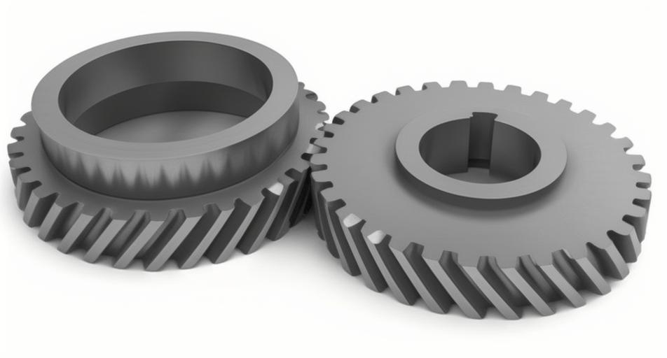
This study investigates the geometric error modeling, real-time monitoring, and compensation strategies for CNC machine tools during the grinding of internal helical gears. A systematic approach combining homogeneous coordinate transformation and multi-body system theory is proposed to enhance machining accuracy.
1. Geometric Error Modeling
The geometric error model for internal helical gear grinding is established using homogeneous coordinate transformation. The ideal coordinate transformation matrix between the workpiece and tool is expressed as:
$$T_{gW} = T_{gC}T_{CX}T_{XJ}T_{JZ}T_{ZA}T_{AW}$$
Considering geometric errors in actual machining, the transformation matrix becomes:
$$T_{gW}^e = T_{gC}^e T_{CX}^e T_{XJ}^e T_{JZ}^e T_{ZA}^e T_{AW}^e$$
The error matrix \(E_{gW}\) is derived as:
$$E_{gW} = T_{gW}^e \cdot (T_{gW})^{-1} = \begin{bmatrix}
1 & -\epsilon_z & \epsilon_y & \delta_x \\
\epsilon_z & 1 & -\epsilon_x & \delta_y \\
-\epsilon_y & \epsilon_x & 1 & \delta_z \\
0 & 0 & 0 & 1
\end{bmatrix}$$
where \(\delta_x, \delta_y, \delta_z\) represent linear errors and \(\epsilon_x, \epsilon_y, \epsilon_z\) denote angular errors along X/Y/Z axes.
2. Multi-body System Analysis
The machine tool structure is decomposed into kinematic chains using multi-body system theory. The low-order body array for the grinding system is summarized as:
| Body Number | L1(K) | L2(K) | L3(K) |
|---|---|---|---|
| 1 (Machine Bed) | 0 | 0 | 0 |
| 2 (X-axis) | 1 | 0 | 0 |
| 3 (C-axis) | 2 | 1 | 0 |
| 5 (Z-axis) | 1 | 0 | 0 |
3. Tooth Surface Error Prediction
The grinding wheel profile is defined in parametric form:
$$r_q(\eta) = [x_q(\eta), y_q(\eta), 0, 1]^T$$
The actual tooth surface considering geometric errors is calculated through coordinate transformation:
$$r_g^e(\eta,\phi) = T_{gW}^e \cdot r_w(\eta,\phi)$$
The contact condition between wheel and helical gear is modified as:
$$f^e(\eta,\phi) = (k_g \times r_g^e + \dot{k}_g) \cdot n_g^e = 0$$
where \(k_g\) represents the gear axis vector and \(n_g^e\) is the normal vector of the error-affected surface.
4. Real-time Monitoring System
A synchronized data acquisition system monitors axis positions during helical gear grinding:
| Axis | Position Range | Tracking Error |
|---|---|---|
| X-axis | 352-372 mm | ±0.01 mm |
| Z-axis | 200-300 mm | ±0.17 mm |
| C-axis | 220-340° | ±0.033° |
The monitoring architecture includes:
- Built-in encoder signal acquisition
- Synchronized data sampling at 1 kHz
- Dynamic error visualization
5. Error Compensation Strategy
Software-based compensation is implemented through:
$$x_{comp} = x_{cmd} + \Delta x(\theta)$$
$$\theta_{comp} = \theta_{cmd} + \Delta \theta(v)$$
where compensation values \(\Delta x\) and \(\Delta \theta\) are determined through reverse error mapping. Key compensation parameters for helical gear grinding include:
| Error Source | Compensation Weight | Update Rate |
|---|---|---|
| Z-axis Positioning | 0.85 | 10 ms |
| C-axis Rotation | 0.92 | 5 ms |
| Thermal Drift | 0.78 | 30 s |
6. Experimental Validation
Helical gear specifications for verification:
| Parameter | Value |
|---|---|
| Module | 2 mm |
| Helix Angle | 15° |
| Number of Teeth | 79 |
| Face Width | 45 mm |
Measurement results show significant error reduction:
| Error Type | Before (μm) | After (μm) |
|---|---|---|
| Total Profile Error | 11.3 | 7.3 |
| Pitch Deviation | 7.9 | 6.2 |
| Cumulative Error | 28.8 | 24.1 |
The proposed methodology demonstrates 34.5% average improvement in helical gear accuracy, validating the effectiveness of geometric error modeling and real-time compensation strategies.
7. Conclusion
This research establishes a comprehensive framework for precision grinding of internal helical gears through:
- Multi-body system based geometric error modeling
- Synchronized multi-axis error monitoring
- Dynamic software compensation
The integration of homogeneous coordinate transformation with real-time data processing provides an effective solution for enhancing the manufacturing accuracy of complex helical gear components.
