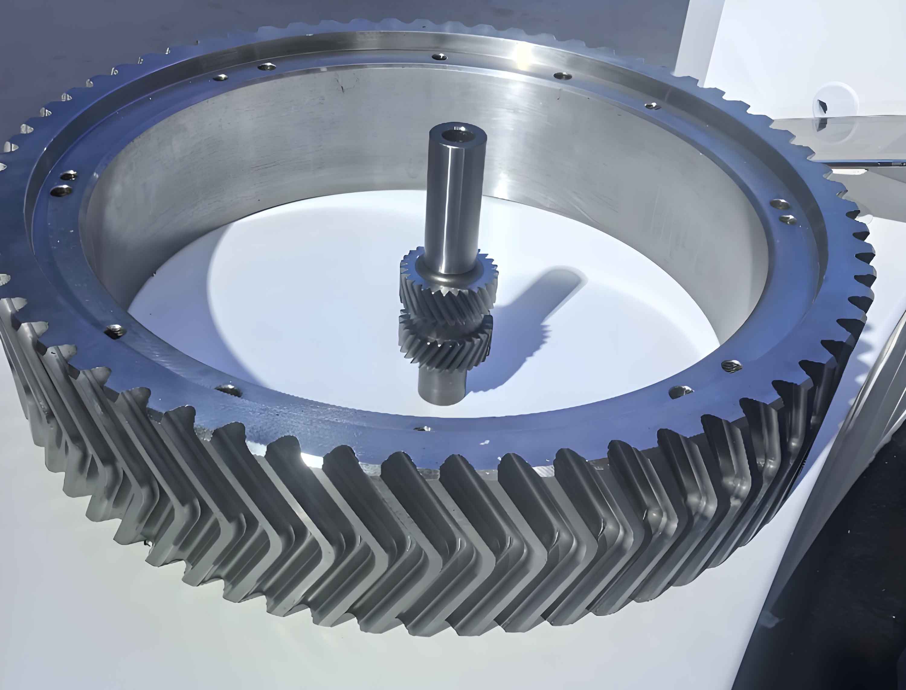
This paper presents an innovative approach for designing six-branch herringbone gear transmission systems with optimized load distribution and interference-free operation. The methodology combines modified gear theory with spatial arrangement analysis to ensure proper meshing conditions across multiple power paths.

1. System Configuration
The six-branch herringbone gear transmission system features coaxial input/output configuration with three-stage power division:
| Stage | Components | Function |
|---|---|---|
| Input Stage | Z₁ (Driver) | Power distribution |
| Intermediate Stage | Z₂₁-Z₂₃ (Idlers) | Torque splitting |
| Output Stage | Z₆ (Driven) | Power convergence |
2. Meshing Interference Conditions
The critical interference condition for four-gear simultaneous meshing in herringbone gear systems is expressed as:
$$ z_4\theta_4 + z_6\theta_6 + 2z_5(360 – \theta_5) = N \cdot 360 $$
Where angular relationships are determined by:
$$ \theta_4 = 180^{\circ} $$
$$ \theta_6 = 2\sin^{-1}\left(\frac{a_{45}}{a_{56}}\right) $$
$$ \theta_5 = 180^{\circ} – \frac{\theta_4 + \theta_6}{2} $$
3. Transmission Ratio Optimization
The system transmission ratio must satisfy:
$$ \frac{i_1 \cdot i_2}{i} – 1 \leq i_e $$
Where stage ratios are calculated as:
$$ i_1 = \frac{z_3}{z_1} $$
$$ i_2 = \frac{z_6}{z_4} $$
| Parameter | Symbol | Constraint |
|---|---|---|
| Adjacency Condition | a₅₅ | ≥ dₐ₅ |
| Coaxial Alignment | a₁₃ | = a₄₆ |
| Module Ratio | m₁/m₂ | ≤ 1.25 |
4. Profile Modification Strategy
For herringbone gear systems requiring micro-adjustment, the profile shift coefficient is determined by:
$$ x_{n45} = \frac{(z_4 + z_5)}{2\tan\alpha_n}(\text{inv}\alpha’_t – \text{inv}\alpha_t) $$
Where modified pressure angle satisfies:
$$ \cos\alpha’_t = \frac{a}{a’}\cos\alpha_t $$
5. Case Study: Marine Transmission System
Implementation parameters for a 36MW herringbone gear system:
| Parameter | Value | Unit |
|---|---|---|
| Input Power | 36,000 | kW |
| Input Speed | 4,000 | rpm |
| Transmission Error | <0.1% | – |
Optimal design solutions for herringbone gear arrangement:
| Solution | z₁-z₂-z₃ | z₄-z₅-z₆ | Volume (m³) |
|---|---|---|---|
| 1 | 53-95-140 | 28-63-212 | 1.518 |
| 2 | 61-103-154 | 28-63-222 | 1.699 |
| 3 | 54-96-138 | 28-69-219 | 1.608 |
6. Dynamic Performance Factors
The load distribution factor for herringbone gears is expressed as:
$$ K_\beta = 1.15 + 0.18\left(\frac{b}{d}\right)^2 + 0.0003b $$
Where contact ratio enhancement from herringbone geometry provides:
$$ \varepsilon_\gamma = \varepsilon_\alpha + \varepsilon_\beta \geq 2.5 $$
7. Manufacturing Considerations
Key production parameters for high-power herringbone gears:
| Process | Tolerance | Surface Finish |
|---|---|---|
| Hobbing | IT6-7 | Ra 1.6-3.2μm |
| Grinding | IT4-5 | Ra 0.4-0.8μm |
The developed methodology enables rapid design of six-branch herringbone gear systems with guaranteed non-interference conditions and optimal load distribution characteristics. The integration of profile modification theory with spatial constraint analysis provides a comprehensive solution for high-power marine transmission applications.
