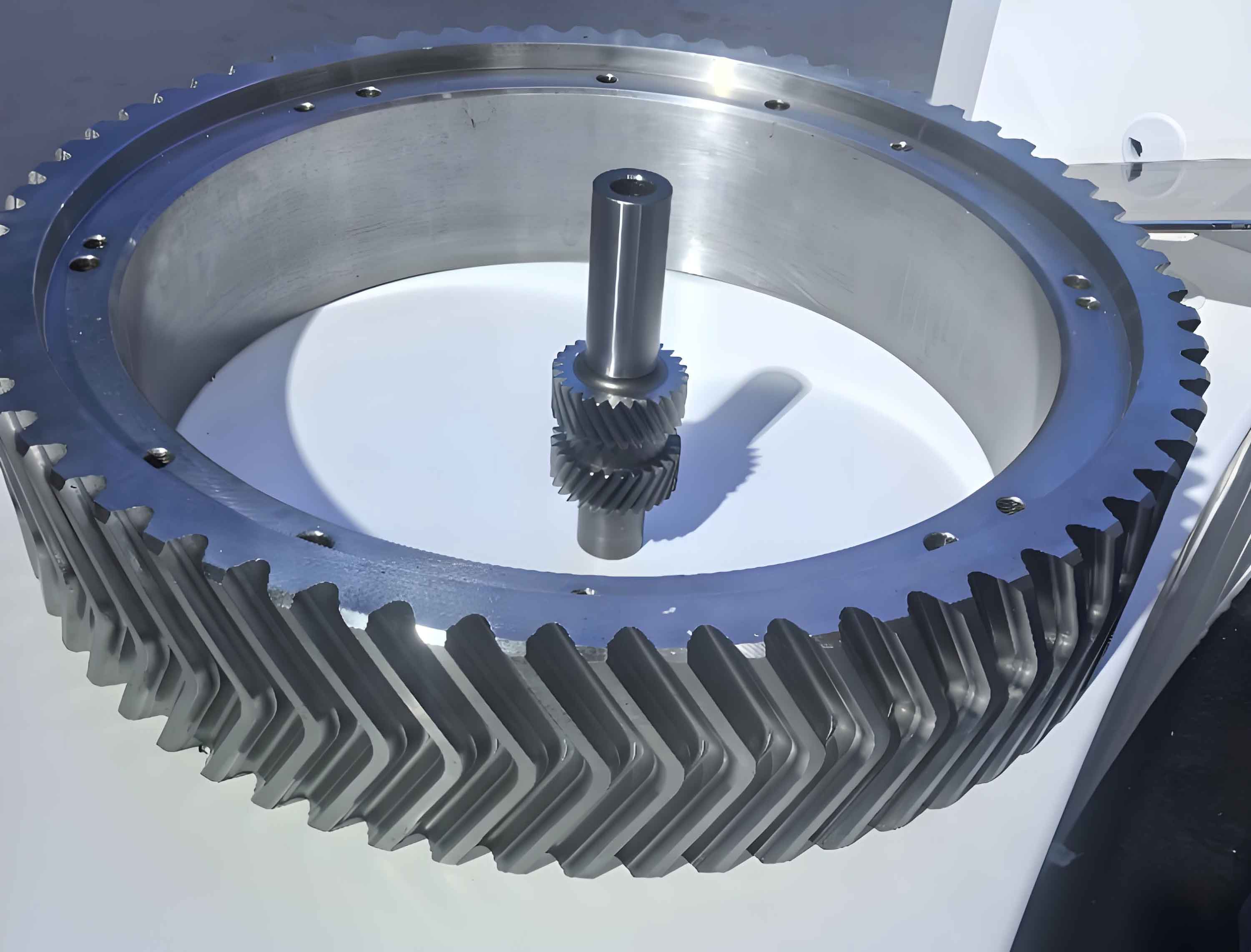
This study investigates the meshing characteristics of herringbone gears under varying lead crowning modifications and staggered tooth arrangements. We propose a novel Newton-Raphson iteration method to solve axial displacement challenges in double helical gear systems, addressing limitations in traditional approaches when handling large-scale manufacturing deviations.
1. Load-Deformation Compatibility Model
The meshing behavior of herringbone gears can be modeled using finite line contact theory combined with structural compliance analysis. For any contact point i, the deformation compatibility equation is expressed as:
$$ \sum_{j=1}^{k} (\lambda_{p_{ij}} + \lambda_{g_{ij}})f_{n_j} + u_{c_i} + d_i = \delta + \epsilon_i $$
Where:
$\lambda_{p/g_{ij}}$ = Compliance coefficients
$f_{n_j}$ = Normal contact force
$u_{c_i}$ = Local contact deformation
$d_i$ = Residual gap
$\delta$ = Relative displacement
$\epsilon_i$ = Initial gap
The axial force balance equation for staggered herringbone gears becomes:
$$ \sum_{i=1}^{k_L} f_{n_i}\cos\alpha\cos\gamma_{L_i} = \sum_{j=1}^{k_R} f_{n_j}\cos\alpha\cos\gamma_{R_j} $$
2. Lead Crowning Modification Effects

Lead crowning modification significantly impacts load distribution and meshing excitation. The crowning profile follows:
$$ C_i = \sqrt{r^2 – \left(\frac{L_i}{\cos\beta_b}\right)^2} – (r – C_{\text{max}}) $$
| Cmax (μm) | Mean km (kN/mm) | Amplitude Δkm | Mean em (μm) |
|---|---|---|---|
| 2 | 1,622.15 | 282.67 | 1.61 |
| 15 | 1,004.10 | 426.93 | 2.25 |
Increasing crowning from 2μm to 15μm reduces mean mesh stiffness by 38% while increasing maximum normal force at tooth center from 100N to 370N.
3. Stagger Angle Influence
The staggered tooth arrangement introduces phase-shifted meshing patterns. For a gear with N teeth, the stagger phase difference γs ranges 0-π, creating load-sharing effects:
$$ \Gamma_s = \frac{\gamma_s P_b}{2\pi} $$
| γs | km Improvement | em Reduction |
|---|---|---|
| 0 | 0% | 0% |
| π/2 | 18% | 43% |
| π | 25% | 79% |
Stagger angles induce oscillatory axial movement governed by:
$$ \eta_z^{(n+1)} = \eta_z^{(n)} – \frac{\Delta F_a^{(n)}}{\Delta F_a^{(n)} – \Delta F_a^{(n-1)}} \cdot (\eta_z^{(n)} – \eta_z^{(n-1)}) $$
4. Dynamic Compensation Mechanism
The proposed Newton-Raphson method demonstrates superior convergence for herringbone gears with manufacturing deviations:
$$ K^{(n)} = \frac{\Delta F_a^{(n)} – \Delta F_a^{(n-1)}}{\eta_z^{(n)} – \eta_z^{(n-1)}} $$
This approach reduces computation time by 70% compared to traditional bisection methods for small deviations (<10μm), while maintaining stability for large stagger angles up to 50% tooth pitch.
5. Load Distribution Characteristics
Tooth load distribution coefficient analysis reveals:
$$ L(x) = \frac{F_{N_p}(x)}{\sum_{x’=1}^q F_{N_p}(x’)} $$
Key findings include:
– 25% stagger reduces edge loading by 62%
– Optimal crowning (6-8μm) balances stiffness and stress concentration
– Combined modifications achieve 54% vibration reduction
6. Conclusion
This comprehensive analysis of herringbone gear meshing behavior demonstrates that:
1. Lead crowning effectively redistributes tooth loads but increases mesh error
2. Staggered tooth arrangements provide dynamic compensation through phase-shifted meshing
3. The proposed Newton-Raphson method enables efficient analysis of asymmetric herringbone gear systems
4. Combined modifications optimize load distribution while minimizing vibration excitation
The methodology and findings provide valuable insights for designing high-performance herringbone gear transmissions in high-speed train applications, particularly addressing challenges in load distribution and dynamic stability.
