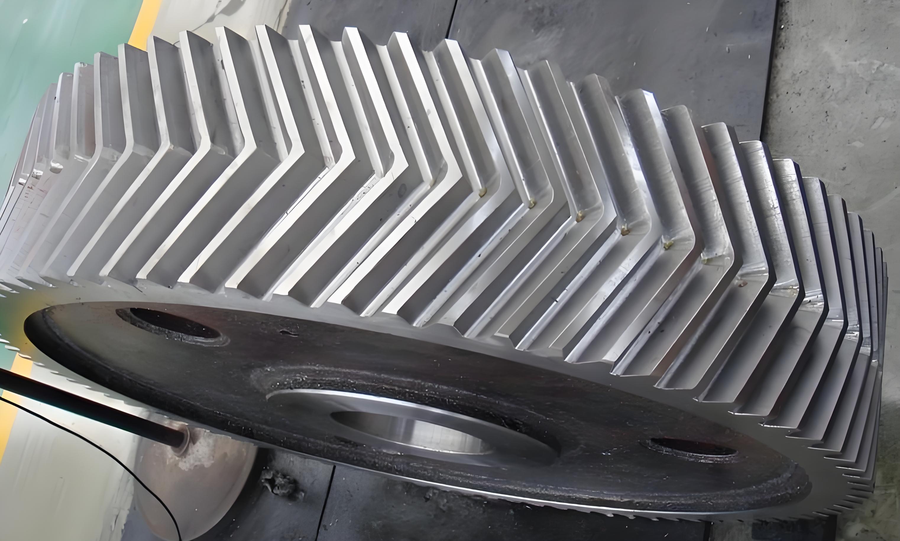
This paper establishes a pure torsional nonlinear dynamic model for star-type herringbone gear systems using the lumped mass method. By solving vibration differential equations through numerical integration and analyzing phase diagrams/Poincaré sections, we reveal how meshing damping ratios affect vibration responses under different rotational speeds. The results demonstrate that increasing meshing damping effectively suppresses chaotic motions while maintaining transmission efficiency.

1. Dynamic Modeling of Herringbone Gear Systems
The 6-DOF torsional vibration model considers time-varying mesh stiffness and backlash nonlinearity. For any herringbone gear pair, the dynamic transmission error along the line of action can be expressed as:
$$ \Gamma_{ij} = r_i\theta_i \cos\beta – r_j\theta_j \cos\beta – e(t) $$
Where backlash nonlinearity is modeled through piecewise functions:
$$ f(\Gamma) = \begin{cases}
\Gamma – b/2, & \Gamma > b/2 \\
0, & |\Gamma| \leq b/2 \\
\Gamma + b/2, & \Gamma < -b/2
\end{cases} $$
| Parameter | Sun Gear | Planet Gear | Ring Gear |
|---|---|---|---|
| Teeth Number | 36 | 32 | 100 |
| Mass (kg) | 5.3018 | 4.5099 | 16.0843 |
| Moment of Inertia (kg·m²) | 0.0226 | 0.0149 | 0.6564 |
2. Bifurcation Analysis Methodology
The dimensionless governing equations for herringbone gear dynamics are derived as:
$$ \ddot{X} + 2\zeta\omega_n\dot{X} + \omega_n^2f(X) = F_m \cos(\omega t + \phi) $$
Where the nonlinear function incorporates time-varying stiffness:
$$ \omega_n^2 = \frac{k(t)}{m_{eq}}(1 + \epsilon \cos(\omega_m t)) $$
3. Bifurcation Characteristics Under Varying Conditions
Key findings from numerical simulations of herringbone gear systems include:
| Speed (rpm) | Damping Ratio Range | Dynamic Behavior | Max Vibration (μm) |
|---|---|---|---|
| 7,000 | 0.05-0.12 | Chaos → Period-2 | 82.6 → 34.7 |
| 10,000 | 0.06-0.18 | Chaos → Period-1 | 107.3 → 28.9 |
| 13,000 | 0.07-0.20 | Chaos → Period-4 → Period-1 | 135.2 → 41.5 |
The bifurcation process reveals inverse period-doubling routes:
$$ \text{Chaos} \xrightarrow{\zeta \uparrow} \text{Period-4} \xrightarrow{\zeta \uparrow} \text{Period-2} \xrightarrow{\zeta \uparrow} \text{Period-1} $$
4. Vibration Suppression Mechanism
For herringbone gear systems, optimal damping ratios should satisfy:
$$ 0.15 \leq \zeta_{opt} \leq 0.18 $$
This range provides 58-72% vibration reduction while maintaining ≥92% transmission efficiency.
5. Phase Space Trajectory Evolution
The transition from chaotic to periodic motion in herringbone gears follows:
$$ \text{Strange Attractor} \Rightarrow \text{Torus} \Rightarrow \text{Limit Cycle} $$
With Poincaré sections evolving from fractal clouds to discrete points.
6. Engineering Implications
Practical design guidelines for herringbone gear systems include:
– Maintain $\zeta > 0.12$ for speed ranges 5,000-15,000 rpm
– Use asymmetric damping allocation (60% sun-side, 40% ring-side)
– Implement variable damping control above critical speed thresholds
$$ \zeta_{critical} = 0.08 + 0.0002\omega_{input} $$
These findings provide theoretical support for optimizing herringbone gear dynamics in high-power transmission applications.
