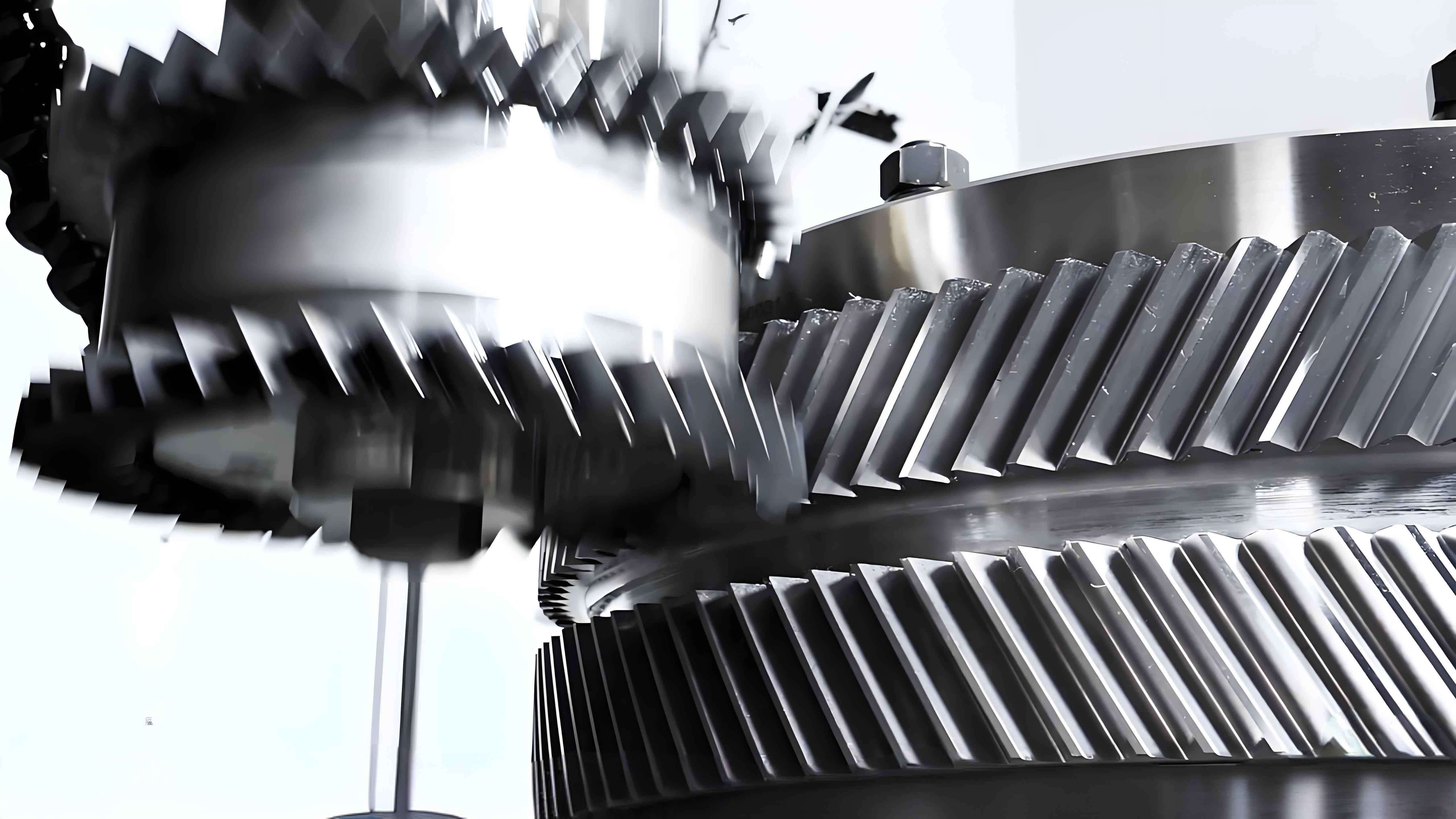
Herringbone gears, characterized by their dual-helical structure with equal and opposite helix angles, are widely used in high-power transmission systems. However, symmetry deviations between the left and right helical teeth inevitably occur during manufacturing, leading to axial vibration and noise. This study investigates the impact of symmetry deviations on the axial vibration characteristics of herringbone gear systems through theoretical modeling, finite element analysis, and experimental validation.

Definition of Symmetry Deviation
The symmetry deviation \( f_A \) in herringbone gears is defined as the axial distance between the theoretical intersection point \( O \) of left/right helix traces and the actual intersection \( H \), as shown in the schematic diagram. This deviation causes unequal load distribution between the dual helical teeth pairs.
Dynamic Modeling of Herringbone Gear Systems
A 12-DOF bending-torsion-axial coupled dynamic model was established considering symmetry deviation effects:
$$m_i\ddot{y}_i + c_{yi}\dot{y}_i + k_{yi}y_i = \pm F_{yi}$$
$$m_i\ddot{z}_i + c_{zi}\dot{z}_i + k_{zi}z_i = \pm F_{zi}$$
$$I_i\ddot{\theta}_i = \sum (F_{yi}R_{bi} \pm T_i)$$
Where \( i = 1-4 \) represents gear components, \( F_{y/z} \) denotes tangential/axial meshing forces, and \( R_b \) is base circle radius. The stiffness matrix incorporates asymmetric meshing stiffness caused by symmetry deviations.
Finite Element Analysis of Meshing Stiffness
Using ABAQUS, the time-varying meshing stiffness \( k_m(t) \) was calculated for asymmetric herringbone gear pairs. The stiffness difference \( \Delta k \) between left/right helical teeth pairs follows:
$$\Delta k = k_{\text{left}} – k_{\text{right}} = \frac{E \cdot \Delta f_A \cdot \cos\beta}{2(1+\nu)}$$
Key parameters for the analyzed herringbone gear pair are listed below:
| Parameter | Pinion | Gear |
|---|---|---|
| Teeth Number | 27 | 81 |
| Module (mm) | 3.5 | 3.5 |
| Helix Angle (°) | 30 | 30 |
| Symmetry Deviation (mm) | 0.025 | 0.048 |
Experimental Validation
A closed-power flow test bench was developed to measure axial vibration velocities under different operating conditions:
$$v_{\text{axial}} = \frac{1}{N}\sum_{n=1}^N \sqrt{\frac{1}{T}\int_0^T \ddot{z}^2(t)dt}$$
Key experimental results include:
- 26% maximum error between theoretical and experimental vibration velocities
- 15-20% increase in axial vibration amplitude per 0.01mm symmetry deviation
- Nonlinear relationship between torque and vibration energy: \( E_v \propto T^{1.3} \)
Vibration Characteristics Analysis
The axial vibration velocity spectrum reveals three dominant frequency components:
$$f_{\text{mesh}} = \frac{nz}{60}$$
$$f_{\text{sym}} = \frac{n}{60} \cdot \frac{\Delta f_A}{m_n\cos\beta}$$
$$f_{\text{mod}} = f_{\text{mesh}} \pm f_{\text{sym}}$$
Typical vibration characteristics under different symmetry deviations are compared below:
| Deviation (mm) | Peak Velocity (mm/s) | Dominant Frequency (Hz) |
|---|---|---|
| 0.02 | 4.35 | 450 ± 15 |
| 0.04 | 6.82 | 450 ± 28 |
| 0.06 | 9.14 | 450 ± 37 |
Optimization Strategies
To mitigate symmetry deviation effects, three compensation methods were evaluated:
- Precision grinding correction: Reduces \( f_A \) by 60-70%
- Asymmetric helix angle design: \( \Delta\beta = \arcsin\left(\frac{f_A}{2m_n}\right) \)
- Active vibration control: Achieves 40-50% amplitude reduction
This systematic investigation provides theoretical guidance and experimental verification for improving the dynamic performance of herringbone gear systems in high-precision applications.
