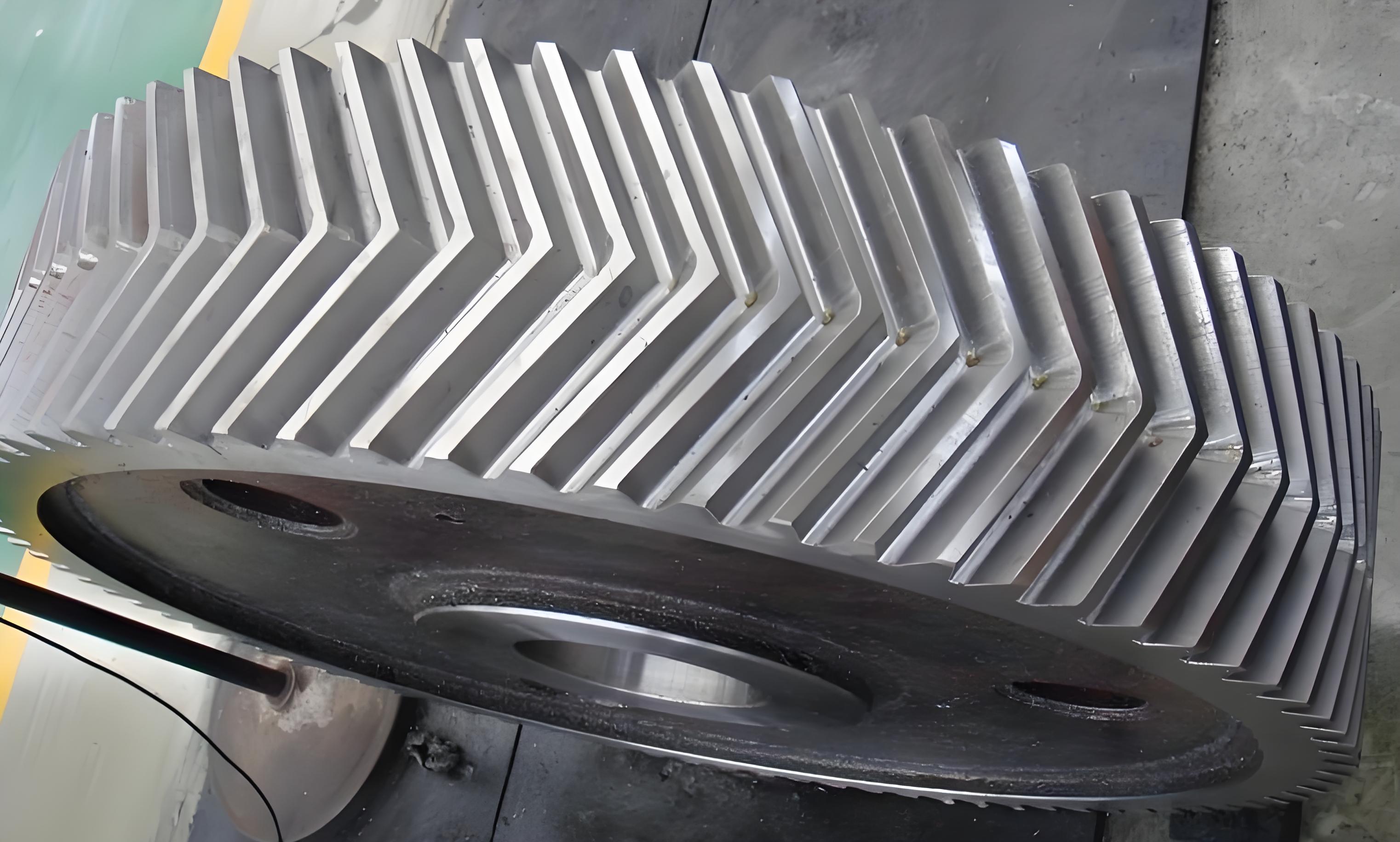
Herringbone gears play critical roles in heavy-duty applications due to their superior load capacity and axial force cancellation. This study investigates vibration characteristics under progressive tooth wear through theoretical modeling and experimental validation.
1. Wear Modeling and Meshing Dynamics
The adhesive wear mechanism follows Archard’s principle, where cumulative wear depth at meshing points is calculated as:
$$ h_{i,j} = h_{i-1,j} + \frac{4 a p k_\iota (v_1 – v_2)}{v_j} $$
where $a$ represents contact half-width, $p$ denotes Hertzian contact pressure, and $k_\iota$ is the wear coefficient. For herringbone gear pairs, wear evolution alters both mesh stiffness and transmission error.
2. Time-Varying Mesh Stiffness Calculation
The total deformation $\delta_{\Xi_j}$ at meshing points combines multiple factors:
$$ \delta_{\Xi_j} = \delta_{Br,j} + \delta_{Bt,j} + \delta_{R,j} + \delta_{pe,j} + h_{i,j} $$
Where components represent bending, shear, base deformation, Hertz contact, and wear depth respectively. The equivalent mesh stiffness becomes:
$$ k_m = \frac{F}{\sum_{i=1}^N \delta_{\Xi_i}} $$
Typical mesh stiffness variations under different wear stages are summarized in Table 1.
| Wear Stage | Depth (μm) | Stiffness Reduction |
|---|---|---|
| Initial Run-in | 0-5 | 2.8% |
| Steady Wear | 5-20 | 12.4% |
| Severe Wear | >20 | 31.7% |

3. Dynamic Model Formulation
A 12-DOF bending-torsional coupled model for herringbone gear systems considers:
$$ M\ddot{X} + C\dot{X} + KX = F_{mesh} $$
Where displacement vector $X$ contains coordinates for both helical halves:
$$ X = [x_p,y_p,z_p,\theta_p,x_g,y_g,z_g,\theta_g]^T $$
Relative mesh displacement $\delta_{mi}(t)$ combines translational and rotational components:
$$ \delta_{mi}(t) = [(y_{pi}-y_{gi})\cos\psi + (x_{pi}-x_{gi})\sin\psi + r_{pi}\theta_{pi} + r_{gi}\theta_{gi}]\cos\beta + (z_{pi}-z_{gi})\sin\beta – e_t $$
4. Experimental Validation
Vibration tests on a herringbone gear test rig revealed:
- Acceleration amplitude increases 58% when speed rises from 100 to 500 rpm at constant torque
- Wear progression causes 11.2% initial vibration reduction followed by 160% increase after 5×10⁷ cycles
Critical frequency components show wear-induced modulation:
$$ A_{mod} = \sum_{n=1}^3 A_n\sin(2\pi nf_m t + \phi_n) $$
where $f_m$ is mesh frequency and $A_n$ represents wear-related sidebands.
5. Wear-Vibration Correlation
The vibration energy index $E_v$ demonstrates strong correlation with wear depth $h_w$:
$$ E_v = 0.024h_w^{1.37} + 0.18\ln(N_{cycles}/10^6) $$
Key operational thresholds were identified:
| Condition | RMS Acceleration (m/s²) | Peak Frequency Shift |
|---|---|---|
| Healthy | < 2.1 | < 3% |
| Moderate Wear | 2.1-3.8 | 3-7% |
| Severe Wear | > 3.8 | > 7% |
6. Maintenance Implications
The derived wear-vibration relationship enables predictive maintenance strategies for herringbone gear systems:
$$ RUL = \frac{h_{critical} – h_{current}}{dh/dt} $$
Where remaining useful life (RUL) is calculated from real-time vibration monitoring and wear rate estimation.
This comprehensive analysis provides both theoretical foundation and practical methodology for condition monitoring of herringbone gear transmissions in aerospace and marine applications.
