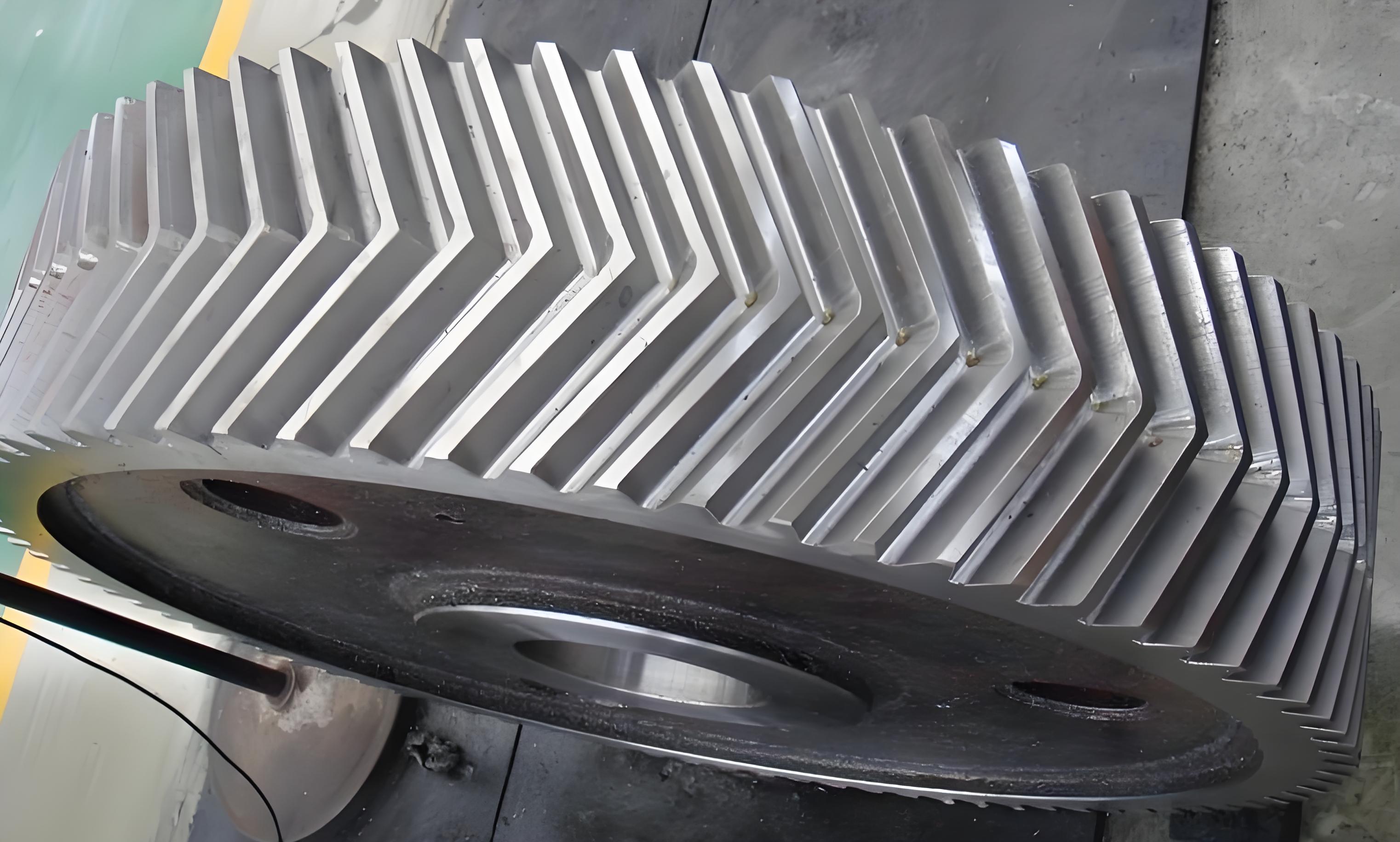
This study investigates the vibration characteristics of two-stage herringbone gear transmission systems under crack-pitting coupling defects. A novel analytical model combining potential energy method and finite element analysis is proposed to quantify time-varying mesh stiffness variations caused by progressive tooth damage.

1. Time-Varying Mesh Stiffness Calculation
The modified potential energy method considers five stiffness components for herringbone gears:
$$k_m = \left[\sum_{i=1}^5 \left(\frac{1}{k_{b1}^i} + \frac{1}{k_{s1}^i} + \frac{1}{k_{a1}^i} + \frac{1}{k_{f1}^i} + \frac{1}{k_{h1}^i} + \frac{1}{k_{b2}^i} + \frac{1}{k_{s2}^i} + \frac{1}{k_{a2}^i} + \frac{1}{k_{f2}^i} + \frac{1}{k_{h2}^i}\right)\right]^{-1}$$
Where subscripts b, s, a, f, and h represent bending, shear, axial compression, foundation, and Hertzian contact stiffness respectively. The crack-pitting coupling effect modifies the effective contact length:
$$l_{eff}(t) = l_0 – \sum_{n=1}^N \left[2\sqrt{R_{sp}^2 – (vt – y_{sp}^n)^2}\right]$$
| Damage Level | Crack Depth (%) | Pitting Radius (mm) | Stiffness Reduction (%) |
|---|---|---|---|
| Stage 1 | 10 | 0.3 | 2.01 |
| Stage 2 | 30 | 0.3 | 4.85 |
| Stage 3 | 50 | 0.4 | 10.40 |
| Stage 4 | 70 | 0.4 | 17.60 |
2. Dynamic Modeling of Herringbone Gear Systems
The 48-DOF dynamic model considers coupled bending-torsional-axial-pendulum motions:
$$M\ddot{X} + C\dot{X} + KX = F(t) + \Delta F_{cp}(t)$$
Where the nonlinear force vector includes crack-pitting effects:
$$\Delta F_{cp}(t) = \sum_{j=1}^{N_m} \left[\Delta k_{m}^j(t)(x_j – e_j(t)) + \Delta c_{m}^j(t)\dot{x}_j\right]$$
3. Vibration Characteristics Analysis
The time-domain response shows periodic impacts corresponding to mesh frequency harmonics:
$$a(t) = \sum_{n=1}^\infty A_n \cos(2\pi n f_m t + \phi_n) + \sum_{k=1}^{N_d} B_k \delta(t – t_k)$$
Frequency-domain features reveal sideband modulation patterns:
$$S(f) = \left|\sum_{m=-M}^M C_m \delta(f – (f_c + mf_r))\right|^2$$
4. Experimental Validation
Vibration tests confirm the theoretical predictions with less than 8% deviation in amplitude measurements:
| Condition | Theoretical (μm) | Experimental (μm) | Error (%) |
|---|---|---|---|
| Healthy | 0.50 | 0.48 | 4.17 |
| Stage 1 | 0.60 | 0.57 | 5.26 |
| Stage 3 | 3.57 | 3.83 | 6.79 |
| Stage 4 | 6.02 | 6.51 | 7.53 |
5. Fault Progression Analysis
The damage coupling effect follows distinct phases:
$$I_{cp} = \begin{cases}
0.82\epsilon_p + 0.18\epsilon_c & \text{(Phase 1: Pitting dominant)} \\
0.55\epsilon_p + 0.45\epsilon_c & \text{(Phase 2: Coupled interaction)} \\
0.21\epsilon_p + 0.79\epsilon_c & \text{(Phase 3: Crack dominant)}
\end{cases}$$
This research establishes a comprehensive framework for assessing crack-pitting coupling effects in herringbone gear systems, providing theoretical support for condition monitoring and remaining life prediction of high-power transmission systems.
