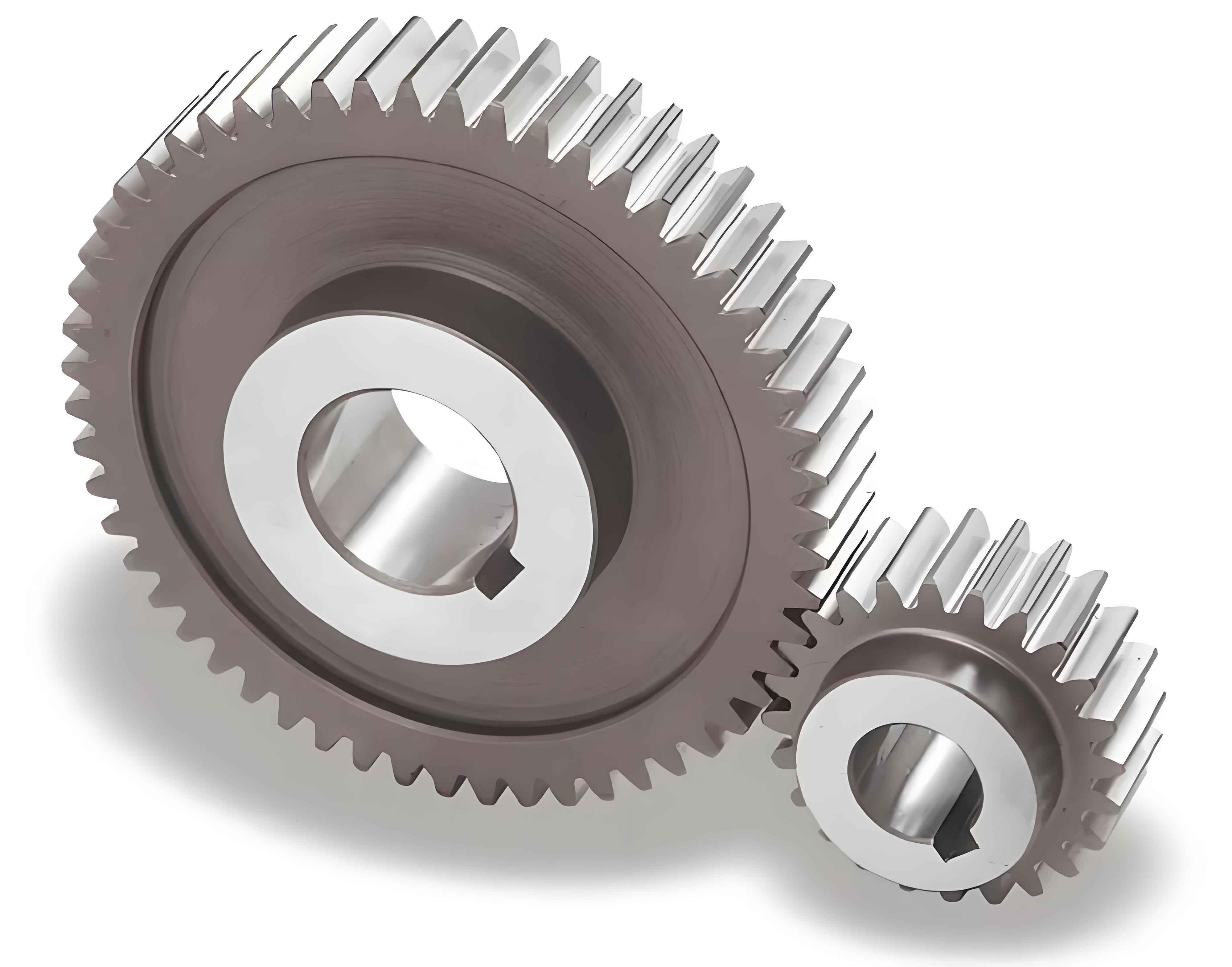
1. Fundamental Requirements for Spur Gear Transmission
Spur gears are critical components in mechanical systems due to their ability to transmit motion and power efficiently. The tooth thickness at any point on the gear profile directly affects load distribution, bending strength, and manufacturing precision. This article systematically derives the formulas for calculating tooth thickness at arbitrary points on standard spur gears.
2. Basic Parameters of Spur Gears
The geometric design of spur gears depends on three primary parameters:
- Module (m): Standardized values shown in Table 1
- Number of teeth (z)
- Pressure angle (α = 20° for standard gears)
| First Series | Second Series |
|---|---|
| 0.1, 0.12, 0.15, …, 50 | 0.35, 0.7, 0.9, …, 45 |
Key geometric relationships for spur gears:
$$ \text{Pitch diameter: } d = mz $$
$$ \text{Base circle diameter: } d_b = mz\cos\alpha $$
$$ \text{Circular pitch: } p = \pi m $$
3. Base Circle Tooth Thickness Calculation
The base circle tooth thickness ($S_b$) forms the foundation for calculating thickness at any point:
$$ S_b = m\cos\alpha\left(\frac{\pi}{2} + z\cdot\text{inv}\alpha\right) $$
Where the involute function is defined as:
$$ \text{inv}\alpha = \tan\alpha – \alpha $$
4. Tooth Thickness at Arbitrary Point K
For any point K on the involute profile with radius $r_K$ and pressure angle $\alpha_K$, the tooth thickness $S_K$ is:
$$ S_K = S\frac{r_K}{r} – 2r_K(\text{inv}\alpha_K – \text{inv}\alpha) $$
Where:
- $S$ = Reference pitch circle thickness ($\frac{\pi m}{2}$)
- $r$ = Pitch circle radius ($\frac{mz}{2}$)
5. Special Case: Root Circle Thickness
For spur gears with $z \geq 42$ teeth (where base circle < root circle), root circle thickness $S_f$ is:
$$ \cos\alpha_f = \frac{z\cos\alpha}{z-2.5} $$
$$ S_f = S\frac{r_f}{r} – 2r_f(\text{inv}\alpha_f – \text{inv}\alpha) $$
| Teeth (z) | Pitch Thickness (mm) | Base Circle Thickness (mm) | Root Circle Thickness (mm) |
|---|---|---|---|
| 20 | 4.712 | 5.268 | – |
| 30 | 4.712 | 5.688 | – |
| 45 | 4.712 | 6.318 | 6.307 |
6. Practical Applications in Spur Gear Design
These calculations enable:
- Accurate bending stress analysis
- Optimal gear tooth profile design
- Precision manufacturing tolerance determination
The derived formulas provide essential tools for engineers working with standard spur gears in power transmission systems, ensuring reliable performance through proper tooth thickness management.
