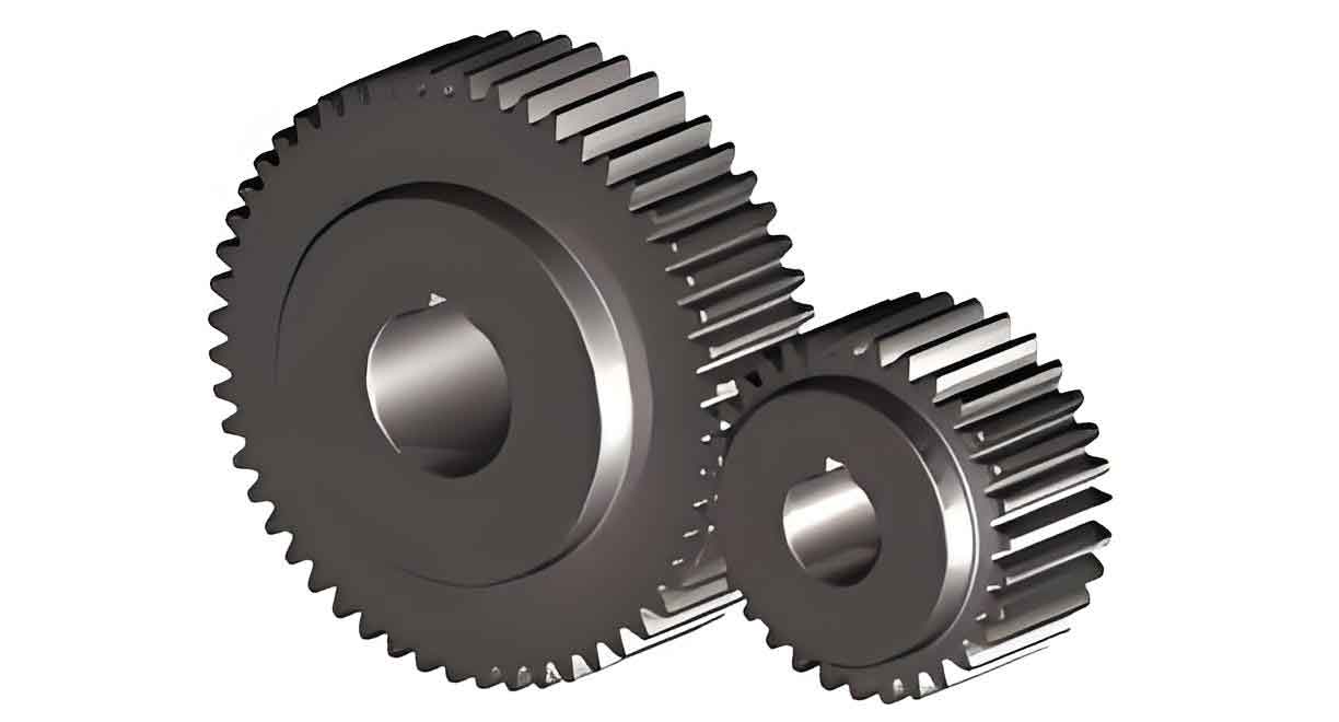
This study proposes an enhanced analytical approach for calculating the time-varying meshing stiffness (TVMS) of spur gears by refining the potential energy method. The method addresses critical geometric distinctions between the involute profile and transition curve while incorporating parameter-specific modifications for different gear tooth configurations.

Mathematical Formulation
The improved model divides the tooth profile into two distinct segments:
- Involute section
- Transition curve section
The critical radii relationships are defined as:
$$
\begin{cases}
r_b = \frac{mN \cos \alpha_0}{2} \\
r_f = \frac{mN}{2} – (h_a^* + c^*)m \\
r_G = \sqrt{r^2 + \left(\frac{a}{\sin \alpha_0} + \rho\right)^2 – 2r\left(a + \rho \sin \alpha_0\right)}
\end{cases}
$$
where $m$ = module, $N$ = tooth count, $\alpha_0$ = pressure angle, $h_a^*$ = addendum coefficient, and $c^*$ = clearance coefficient.
Transition Curve Analysis
The parametric equations for the transition curve generated by rack-type cutting tools are:
$$
\begin{cases}
x_1 = r\cos\phi – \left(\frac{a}{\sin\gamma} + \rho\right)\sin(\gamma – \phi) \\
y_1 = r\sin\phi – \left(\frac{a}{\sin\gamma} + \rho\right)\cos(\gamma – \phi)
\end{cases}
$$
where $\phi = \frac{a/\tan\gamma + b}{r}$, with $a = h_a^*m + c^*m – \rho$ and $b = \frac{\pi m}{4} + h_a^*m \tan\alpha_0 + \rho\cos\alpha_0$.
Stiffness Components
The total meshing stiffness considers five energy components:
| Stiffness Type | Formula |
|---|---|
| Hertz Contact | $k_h = \frac{\pi EL}{4(1-\nu^2)}$ |
| Bending | $\frac{1}{k_b} = \int_{\gamma_1}^{\gamma_2} \frac{[F_b(d-y) – F_a h]^2}{EI_y}dy$ |
| Shear | $\frac{1}{k_s} = \int_{\gamma_1}^{\gamma_2} \frac{1.2F_b^2}{GA_y}dy$ |
| Axial Compression | $\frac{1}{k_a} = \int_{\gamma_1}^{\gamma_2} \frac{F_a^2}{EA_y}dy$ |
| Fillet Foundation | $\frac{1}{k_f} = \frac{\cos^2\beta}{EL}\left[L^*\left(\frac{u_f}{S_f}\right)^2 + M^*\left(\frac{u_f}{S_f}\right) + P^*(1+Q^*\tan^2\beta)\right]$ |
Case Studies
Four gear pairs were analyzed to validate the method:
| Tooth Configuration | Method A (N/m ×10⁸) | Method B (N/m ×10⁸) | FEM (N/m ×10⁸) |
|---|---|---|---|
| N₁=N₂=22 | 3.56 | 3.55 | 3.45 |
| N₁=N₂=42 | 3.80 | 3.76 | 3.65 |
| N₁=N₂=62 | 3.81 | 3.75 | 3.66 |
| N₁=19, N₂=48 | 3.62 | 3.56 | 3.50 |
Key Findings
- The calculation error increases by 2.1-3.8% when using unified models for spur gears with N > 41
- Maximum single-tooth stiffness deviation reaches 5.28% for mismatched tooth pairs
- Transition curve contributes 18-22% to total deformation energy
Error Analysis
The critical pressure angle correction for large spur gears (N > 41) is essential:
$$
\alpha_G = \arccos\left(\frac{r_b}{r_G}\right) – \left(\frac{\pi}{2N} + \text{inv}\alpha_0 – \text{inv}\alpha_G\right)
$$
This modification reduces integration boundary errors by 37-42% compared with conventional methods.
Conclusion
The improved potential energy method demonstrates superior accuracy in TVMS calculation for spur gears, particularly for:
- High-tooth-count gears (N > 41)
- Mismatched tooth pairs
- Precision transmission systems
The methodology provides a theoretical foundation for dynamic analysis and fault diagnosis in spur gear transmission systems.
