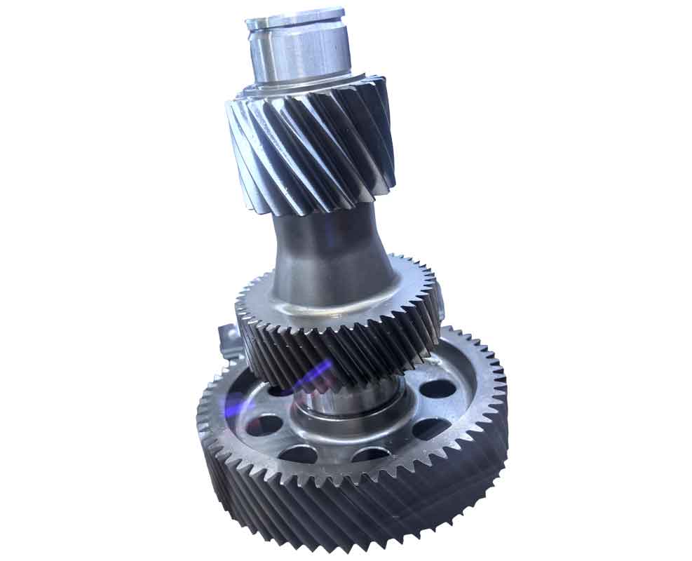
Wind turbine gearboxes represent critical components in renewable energy systems, where bearing failures account for 64% of gearbox malfunctions according to NREL data. Understanding fatigue crack initiation and propagation in bearings is essential for advancing gear technology reliability. This research establishes fundamental relationships between stress fields, material microstructure, and crack behavior using multiaxial fatigue theory and fracture mechanics.
Crack Initiation Direction: Multiaxial Fatigue Framework
Bearing roller-raceway contacts exhibit non-proportional multiaxial stress states. Crack initiation follows the critical plane approach, where initiation occurs along the plane of maximum shear stress amplitude ($\tau_{amp}$). The modified McDiarmid criterion governs this process:
$$ \tau_{amp} + C_1 (\sigma_{amp} + \sigma_{mean}) = C_2 $$
where $\sigma_{amp}$ and $\sigma_{mean}$ denote normal stress amplitude and mean stress on the critical plane, respectively, and $C_1$, $C_2$ are material constants. For homogeneous materials, cracks initiate at maximum $\tau_{amp}$ locations; for heterogeneous materials (e.g., inclusions or WEA), cracks form along interfaces experiencing peak $\tau_{amp}$.
Hertz contact stresses beneath the raceway determine $\tau_{amp}$ distribution. For a cylinder-on-plane model:
$$
\begin{align*}
\sigma_{xx} &= -\frac{p_H z}{\pi b} \left[ (b^2 + 2z^2 + 2x^2)\Phi_1 – 2\pi – 3xb\Phi_2 \right] \\
\sigma_{zz} &= -\frac{p_H z}{\pi} (b\Phi_1 – x\Phi_2) \\
\sigma_{zx} &= -\frac{p_H z^2 \Phi_2}{\pi}
\end{align*}
$$
Principal shear stress ($\tau_n$) and orthogonal shear stress ($\sigma_{zx}$) amplitudes vary with depth ($z$):
| Depth (mm) | Orthogonal $\tau_{amp}$ (MPa) | Principal $\tau_{amp}$ (MPa) | Dominant Stress |
|---|---|---|---|
| 0.1 | 418 | 320 | Orthogonal |
| 0.5 | 380 | 295 | Orthogonal |
| 1.0 | 290 | 275 | Orthogonal |
| 1.5 | 175 | 220 | Principal |
| 2.0 | 95 | 190 | Principal |
Crack initiation angles $\theta_c$ relative to the raceway surface follow:
$$ \theta_c = \begin{cases}
0^\circ & \text{(shallow initiation, } z < 1.2 \text{ mm)} \\
45^\circ & \text{(deep initiation, } z > 1.5 \text{ mm)}
\end{cases} $$
Crack Propagation: Fracture Mechanics Analysis
Propagation direction depends on crack-tip stress superposition. For a surface-initiated crack under Hertz contact, residual stress ($\sigma_R$), and interference fit stress ($\sigma_t$), the polar coordinate stresses are:
$$
\begin{align*}
\sigma_{\theta\theta}^{\text{total}} &= \underbrace{\frac{K_{\text{II}}}{\sqrt{2\pi r}} \sin\frac{\theta}{2} \left(-3\cos^2\frac{\theta}{2}\right)}_{\text{Mode II}} + \underbrace{[(\sigma_{xx} + \sigma_R + \sigma_t)\sin^2\theta + \sigma_{zz}\cos^2\theta]}_{\text{Contact/Residual}} \\
\sigma_{r\theta}^{\text{total}} &= \underbrace{\frac{K_{\text{II}}}{\sqrt{2\pi r}} \cos\frac{\theta}{2} \left(1 – 3\sin^2\frac{\theta}{2}\right)}_{\text{Mode II}} – \underbrace{[(\sigma_{xx} + \sigma_R + \sigma_t) – \sigma_{zz}]\sin\theta\cos\theta}_{\text{Contact/Residual}}
\end{align*}
$$

Residual stress magnitudes vary significantly with heat treatment:
| Material | Heat Treatment | $\sigma_R$ (MPa) | Crack Path Angle |
|---|---|---|---|
| Martensitic Steel | Oil Quench (40°C) | +40 to +100 | 90° to surface |
| Bainitic Steel | Nitrate Quench (210°C) | -200 | 0° to surface |
| Carburized Steel | Case Hardening | -100 | 15° to surface |
Propagation direction $\theta_p$ follows maximum circumferential stress ($\sigma_{\theta\theta}^{\max}$):
$$ \frac{\partial \sigma_{\theta\theta}^{\text{total}}}{\partial \theta} = 0 \quad \text{at} \quad \theta = \theta_p $$
Positive $\sigma_R$ (martensitic) promotes Mode I propagation ($\theta_p ≈ 90^\circ$), while compressive $\sigma_R$ (bainitic) suppresses Mode I, enabling Mode II growth ($\theta_p ≈ 0^\circ$) when:
$$ \Delta K_{\text{II}} > \Delta K_{\text{II,th}} $$
Implications for Gear Technology
These findings directly impact gear technology through:
- Bearing Selection: Bainitic steels provide superior resistance to through-thickness cracking in high-stress wind turbine gearboxes.
- Residual Stress Engineering: Compressive residual stresses ≥ -150 MPa extend bearing L10 life by suppressing Mode I propagation.
- Failure Analysis: Crack angles indicate initiation depth:
- Shallow spalls: 0° initiation → orthogonal shear dominance
- Deep axial cracks: 45° initiation → principal shear dominance
In gear technology applications, interference fits must be optimized using:
$$ \sigma_t = \frac{E \delta}{d} \left( \frac{d^2}{d_o^2 – d^2} \right) $$
where $E$ = Young’s modulus, $\delta$ = interference, $d$ = bore diameter, $d_o$ = outer diameter. Excessive $\sigma_t$ negates compressive $\sigma_R$ benefits.
Conclusions
- Crack initiation direction depends on depth-dependent shear stress amplitudes: orthogonal shear dominates above 1.2 mm (0° initiation), principal shear below 1.5 mm (45° initiation).
- Residual stresses govern propagation: tensile $\sigma_R$ promotes vertical Mode I growth; compressive $\sigma_R$ enables parallel Mode II propagation.
- Heat treatment selection is critical in gear technology—bainitic processing provides optimal $\sigma_R$ for shallow spalling containment.
- Interference fits must be balanced with residual stresses to avoid synergistic tensile effects.
These principles provide a foundation for next-generation wind turbine bearing design, enhancing reliability through physics-based gear technology methodologies.
