
Metal Injection Molding (MIM) has revolutionized gear technology by enabling mass production of small, geometrically complex metal components under 50g. While iron-based alloys dominate this sector, achieving precision in spur gears – characterized by repetitive features and micron-level tolerances – remains challenging due to thickness-direction deviations. This study addresses distortion control in 17-4PH precipitation-hardening stainless steel spur gears, optimizing MIM processing to exceed AGMA Q9 standards. Our gear technology approach integrates mold compensation strategies with parametric adjustments across injection, debinding, and sintering stages.
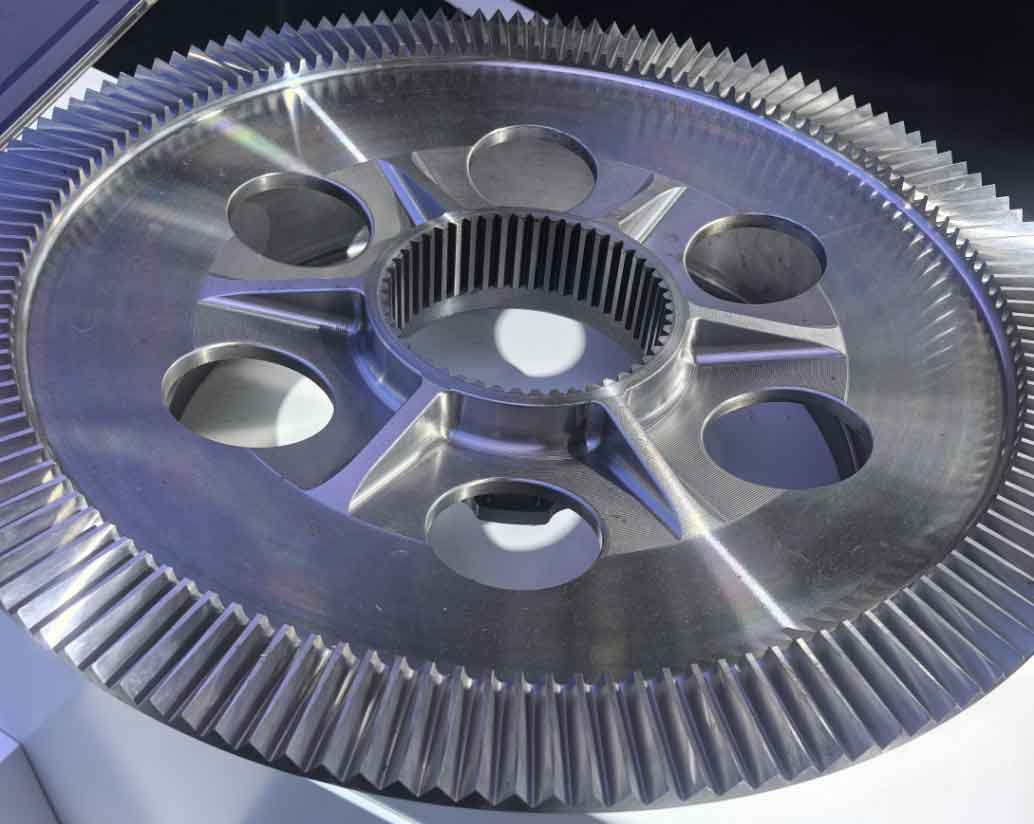
The spur gear design (Figure 1) incorporated a stepped hub for realistic assembly simulation. Critical dimensions included:
| Parameter | Value | Tolerance |
|---|---|---|
| Module | 0.65 mm | – |
| Teeth Count | 25 | – |
| Face Width | 3.80 mm | ±0.05 mm |
| Outer Diameter | 17.18 mm | +0.02/-0.1 mm |
| Root Diameter | 14.34 mm | 0/-0.1 mm |
| Base Tangent Length (4 teeth) | 6.798 mm | -0.051/-0.101 mm |
Mold design employed an Oversize Shrinkage Factor (OSF) derived from feedstock characterization:
$$ \text{OSF} = 1 + \alpha(T_{\text{sinter}} – T_{\text{room}}) + \beta\phi $$
Where α is thermal expansion coefficient, β is powder packing density factor, and φ is solid loading. For 63.2 vol% 17-4PH feedstock (D50=7.9 μm), OSF=1.165±0.005 was implemented. Central gating ensured uniform filling, critical for gear technology applications requiring concentricity.
Processing parameters were systematically optimized through design of experiments (DoE):
| Process Stage | Parameter | Baseline | Optimized |
|---|---|---|---|
| Injection | Melt Temperature | 180°C | 195°C |
| Hold Pressure | 60 MPa | 75 MPa | |
| Cooling Time | 15 s | 22 s | |
| Debinding | Oxalic Acid Catalysis | 110°C/4h | 120°C/6h |
| Sintering | Temperature | 1280°C | 1300°C |
| Hold Time | 1 h | 3 h | |
| Atmosphere | Vacuum | Ar + 50 mbar H2 |
Initial trials revealed thickness-direction deviation patterns conforming to a hyperbolic distortion model:
$$ \delta_z = k \left( \frac{\partial \rho}{\partial z} \cdot \Delta T \cdot t \right) + C $$
Where δz is axial distortion, k is material constant, ∂ρ/∂z is density gradient, ΔT is thermal gradient, t is time, and C is gravity-induced sag. Measurements showed 0.07-0.08 mm deviation from gate-to-ejector sides (Figure 2), compromising gear technology precision requirements.
Mold compensation was implemented through tapered wire-EDM machining, creating a progressive cavity correction:
$$ \Delta D_{\text{mold}} = \delta_z \cdot \text{OSF} \cdot \cos\theta $$
Where θ=1.2° taper angle optimized for 17-4PH shrinkage anisotropy. This advanced gear technology approach pre-distorted the cavity by 40-60 μm across the face width.
Final results demonstrated significant improvement in gear technology metrics:
| Parameter | Initial (mm) | Optimized (mm) | AGMA Q9 Limit |
|---|---|---|---|
| Thickness Deviation | 0.07-0.08 | 0.02-0.03 | 0.04 |
| Outer Diameter Variation | 0.073 | 0.022 | 0.035 |
| Base Tangent Length Tolerance | 0.064 | 0.014 | 0.025 |
| Tooth-to-Tooth Error | 32 μm | 11 μm | 18 μm |
Material properties achieved industry benchmarks crucial for gear technology applications:
$$ \rho = 7.785-7.798\ \text{g/cm}^3\ (99.2-99.4\%\ \text{theoretical}) $$
$$ \text{HV}_{0.1} = 273-287 $$
Microstructural analysis revealed homogeneous precipitation of ε-Cu particles (20-50 nm) after H900 treatment, enhancing gear technology performance under cyclic loading.
Critical findings for gear technology development include:
- Density gradients exceeding 0.15 g/cm3 per mm thickness induce predictable distortion patterns
- Gate-side cooling rates 40% higher than ejector-side create asymmetric shrinkage
- Optimal ceramic setters require 8-12 μm Ra surface texture to prevent Nb-induced adhesion
- Magnetic abrasive finishing must be limited to ≤0.2 mm media with ≤30 min exposure
This systematic approach to gear technology demonstrates that MIM can achieve AGMA Q9 precision when integrating:
- Anisotropic shrinkage modeling
- Thermal gradient management during sintering
- Mold geometry compensation
- Surface interaction control
Future gear technology developments should implement conformal cooling and AI-driven shrinkage prediction to target Q10 precision.