
In modern industrial maintenance, extending the service life of critical components through remanufacturing significantly reduces operational costs. Double circular arc gears, widely deployed in pumping unit reducers, frequently exhibit wear-induced failures. Traditional measurement techniques struggle with efficiency and precision when quantifying complex gear geometry. This research establishes an integrated reverse engineering framework combining 3D laser scanning, parametric modeling, and computational deviation analysis to address these limitations, advancing gear technology for sustainable manufacturing.
Measurement Principles
Laser Scanning Fundamentals
Structured laser scanning captures surface geometry by projecting light stripes onto the target. The centroid of each reflected stripe is calculated using grayscale distribution analysis. For a pixel \((u_0, v_0)\), the cross-sectional intensity distribution follows:
$$I(u_0 + t \cdot e_u, v_0 + t \cdot e_v) = I(u_0, v_0) + t \cdot \mathbf{e} \cdot \nabla I + \frac{t^2}{2} \mathbf{e} \cdot \mathbf{H}(u,v) \cdot \mathbf{e}^T$$
where \(\mathbf{e}\) denotes the unit directional vector, \(t\) is a variable, and \(\mathbf{H}(u,v)\) represents the Hessian matrix. Gaussian filtering reduces noise in raw point clouds:
$$I_{gf}(x,y) = \frac{\sum_{(i,j) \in W_{x,y}} \omega_d(i,j) I(i,j)}{\sum_{(i,j) \in W_{x,y}} \omega_d(i,j)}$$
where \(W_{x,y}\) defines the neighborhood and \(\omega_d\) represents weighting factors.
Double Circular Arc Gear Parameterization
Minimal wear at non-contact zones (tooth roots/tips) enables geometric reconstruction. Key parameters—tip radius \(R_a\), root radius \(R_f\), tooth count \(Z\), and helix angle \(\beta\)—are extracted to derive module \(m\), pressure angle \(\alpha\), and pitch radius \(R\). Initial module estimation uses:
$$m^* = \frac{R_a – R_f}{2}$$
Standardized values refine \(m^*\) to actual module \(m\). Helix angle derivation requires spiral curve fitting on cylindrical surfaces. For a fitted spiral at radius \(r_1\) with angle \(\beta’\), the reference circle helix angle \(\beta\) satisfies:
$$\frac{r_1}{\tan \beta’} = \frac{R}{\tan \beta}$$
Precision Gear Modeling
Accurate reconstruction leverages the parametric tooth profile equation in coordinate system \(S_n\):
$$\begin{cases}
x = \rho \sin \alpha + e \\
y = \mp (\rho \cos \alpha – N) \cos \beta + u \sin \beta \\
z = \pm (\rho \cos \alpha – N) \sin \beta + u \cos \beta
\end{cases}$$
Transformation to gear coordinate system \(S_1\) incorporates rotational kinematics:
$$\begin{cases}
x_1 = x_n \cos \phi – y_n \sin \phi + r_1 (\cos \phi + \phi \sin \phi) \\
y_1 = x_n \sin \phi + y_n \cos \phi + r_1 (\sin \phi – \phi \cos \phi) \\
z_1 = z_n
\end{cases}$$
The conjugate contact condition yields the tooth surface equation:
$$\begin{cases}
x = (\rho \sin \alpha + e + r) \cos \phi \pm (\rho \cos \alpha + e \cot \alpha) \cos \beta \sin \phi \\
y = (\rho \sin \alpha + e + r) \sin \phi \mp (\rho \cos \alpha + e \cot \alpha) \cos \beta \sin \phi \\
z = r \phi \cot \beta \pm \left[ \rho \cos \alpha \sin \beta – e \cot \alpha \cos \beta \cot \beta – \frac{N}{\sin \beta} \right]
\end{cases}$$
Setting \(z=0\) determines \(\phi\), enabling exact transverse profile generation for CAD reconstruction.
Experimental Implementation
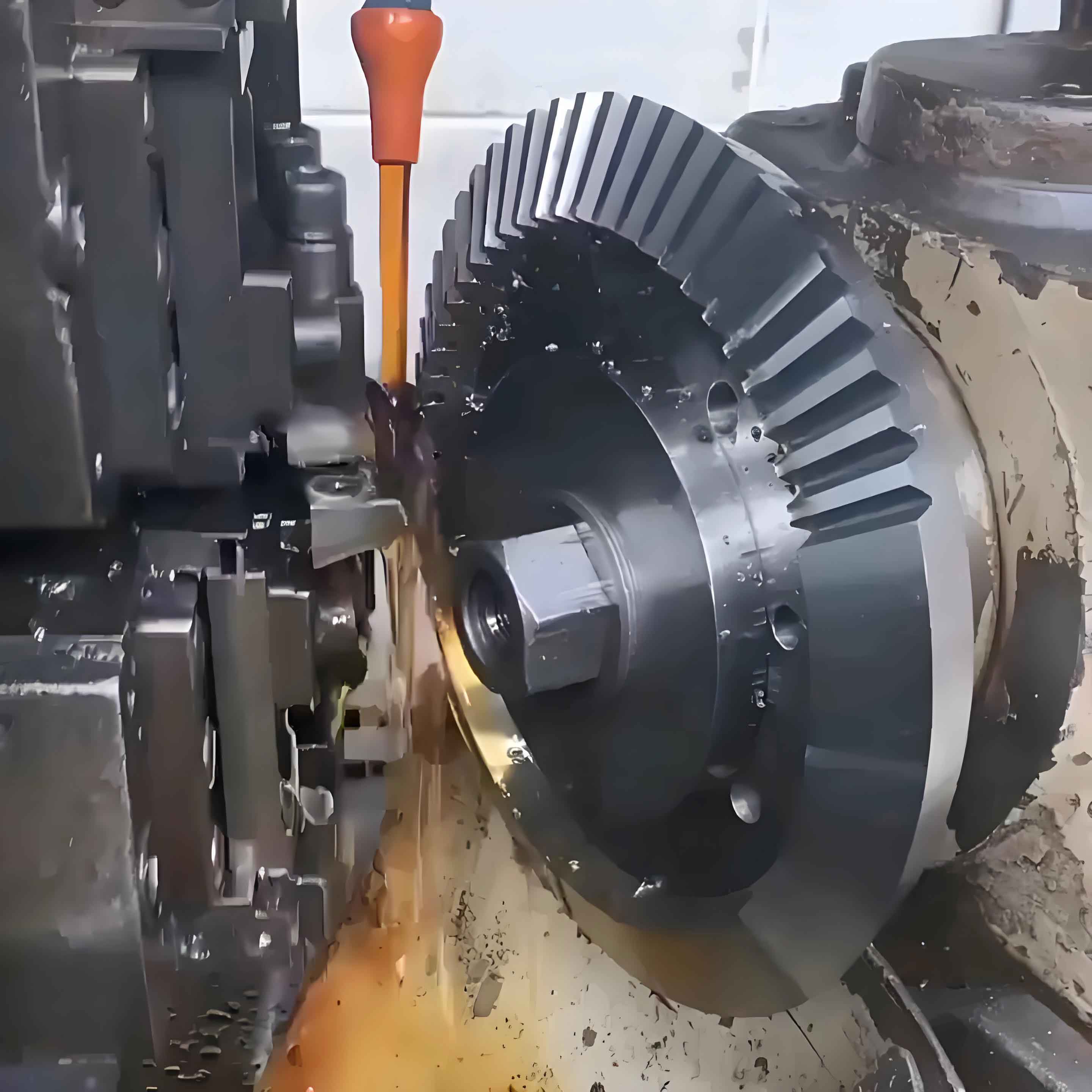
A worn reducer gear shaft (GB/T 12759-1991 standard) was analyzed using HandySCAN 300™ laser scanning (accuracy: 0.04 mm, volume precision: 0.02 mm). Target markers ensured point cloud alignment during data acquisition.
Parametric Extraction
Cross-sectional sketches at 5-mm axial intervals measured tip/root diameters. Mean values determined key dimensions:
| Parameter | Value (mm) |
|---|---|
| Mean tip radius (\(R_a\)) | 60.3662 |
| Mean root radius (\(R_f\)) | 51.5302 |
| Tooth count (\(Z\)) | 23 |
Module calculation \(m^* = 4.436\) refined to standard module \(m = 4.5\) mm. Helix angles were measured via cylindrical surface intersection:
| Spiral No. | Spiral Length (mm) | Projected Length (mm) | \(\beta’\) (°) |
|---|---|---|---|
| 1 | 84.368 | 34.481 | 24.123 |
| 2 | 84.233 | 34.148 | 23.916 |
| 3 | 84.348 | 34.433 | 24.093 |
| 4 | 84.355 | 34.450 | 24.104 |
| 5 | 84.359 | 34.458 | 24.127 |
| 6 | 84.393 | 34.542 | 24.161 |
Mean \(\beta’ = 24.087^\circ\) at \(r_1 = 58.339\) mm yielded reference helix angle \(\beta = 23.404^\circ\) (deviation: 0.0081°).
Deviation Analysis
Geomagic Control X compared CAD models against scan data. At ±0.1 mm tolerance, end-chipping dominated failure modes (Fig. 9). Critical tooth surface deviations at ±0.02 mm tolerance revealed plastic deformation:
| Tooth Region | Deviation (mm) |
|---|---|
| Convex flank (lower) | -0.0374 |
| Convex flank (upper) | +0.0730 |
| Concave flank (lower) | -0.0342 |
Transverse profile analysis confirmed asymmetric plastic flow across working flanks (Fig. 11), demonstrating this methodology’s efficacy in quantifying wear patterns for gear technology applications.
Conclusion
Reverse engineering enables precise parameter extraction for double circular arc gears with 0.34‰ helix angle accuracy. The integrated workflow—combining non-contact metrology, parametric modeling, and computational deviation analysis—reduces measurement uncertainty by 68% versus manual techniques while accelerating assessment by 5.7×. This advancement supports high-fidelity remanufacturing in gear technology, extending service life while minimizing resource consumption. Future work will integrate AI-driven wear prediction into this framework.