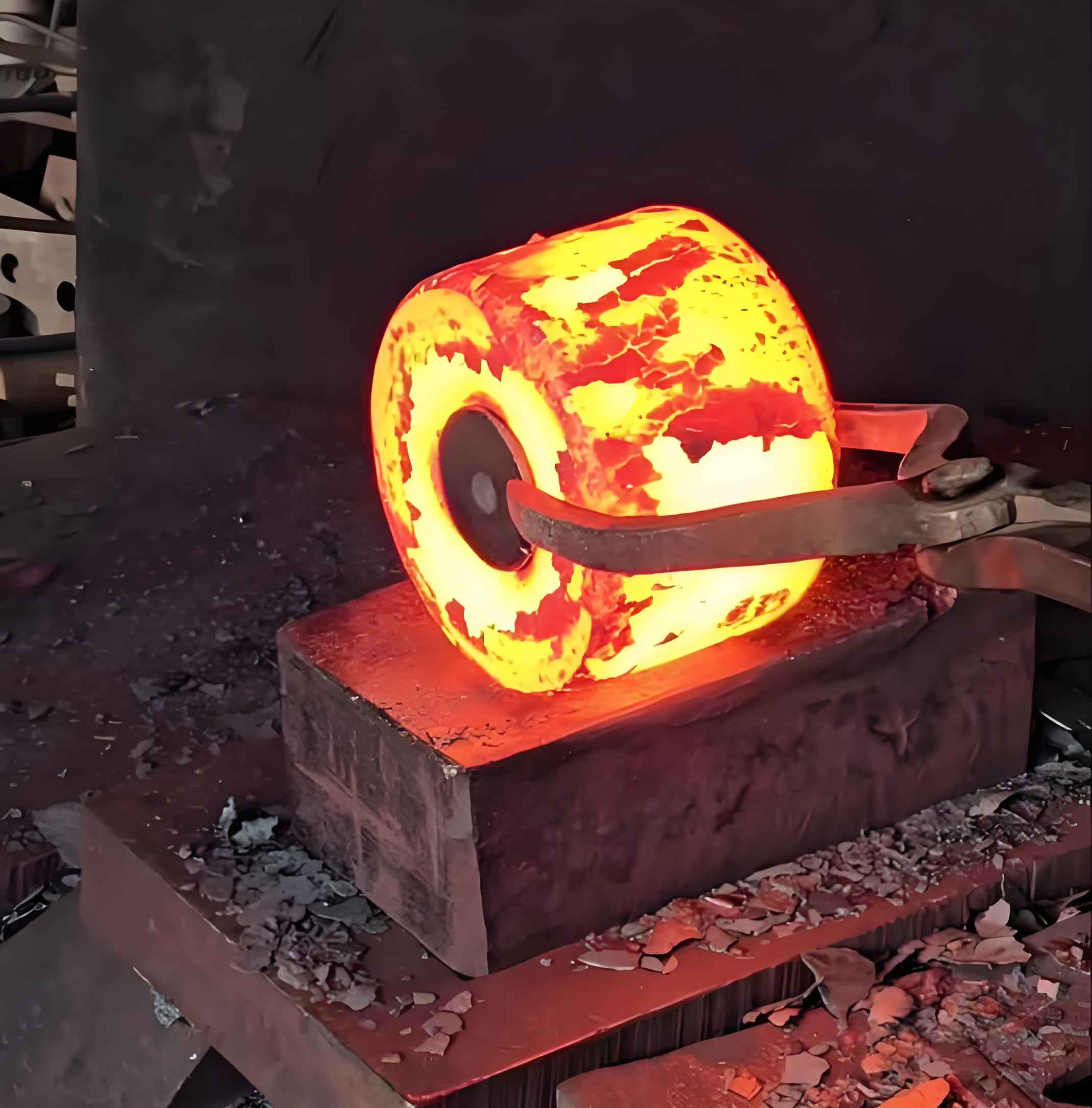
Traditional forging production relied on manual feeding with rudimentary positioning blocks and operator experience, leading to imprecise placement, low efficiency, and high labor intensity. Technological advancements introduced Programmable Logic Controllers (PLCs), simplifying programming, enhancing operational stability, ensuring precise positioning, and resisting external interference. This innovation significantly boosted productivity, enabling the adoption of PLC-based servo-driven step beam automatic feeding systems for multi-station hot forging presses. This research focuses on optimizing such a system specifically for forged gear blank manufacturing across four forming stations.
The core process for forged gear blank production involves heating raw stock to forging temperature, transferring it via coordinated press and step beam actions, and conveying the finished blank. The step beam manipulator executes a precise cyclic sequence: Clamp, Lift, Advance, Lower, Release, Retract, and re-Clamp (CLALDRC cycle). This cycle synchronizes with the press stroke, enabling material handling across stations like storage, upsetting, forming, trimming, and ejection. Its motion equation is defined in three axes:
$$ \vec{P}(t) = [X(t), Y(t), Z(t)] $$
where \( X(t) \) represents horizontal translation, \( Y(t) \) clamping actuation, and \( Z(t) \) vertical elevation. Three-coordinate transfer systems are categorized as follows:
| Feature | Mechanical System | Electronic Servo System |
|---|---|---|
| Drive Source | Mechanical linkage to press crankshaft | Servo motors with PLC control |
| Synchronization | Fixed cam profiles | Electronic signals exchanged with press |
| Trajectory Adaptability | Fixed, non-adjustable | Programmable via PLC, adjustable die spacing |
| Maintenance Complexity | Higher (mechanical wear) | Lower (modular components) |
This study employs an electronic servo system for its superior flexibility in handling diverse forged gear blank geometries. The four-station step beam manipulator utilizes a floor-mounted structure for enhanced rigidity. Its kinematic chain integrates servo motors driving ballscrews/timing belts:
$$ \theta_m = K_p \cdot e(t) + K_i \int e(t) dt + K_d \frac{de(t)}{dt} $$
where \( \theta_m \) is the motor angle, \( e(t) \) the position error, and \( K_p, K_i, K_d \) PID gains. Key structural components include:
| Component | Function | Specification |
|---|---|---|
| Crossbeam (X-axis) | Horizontal translation between dies | Linear guides, servo motor, reducer |
| Lift Column (Z-axis) | Vertical elevation/lowering | Precision ballscrew, 500kg load capacity |
| End Effector (Y-axis) | Workpiece clamping/release | Pneumatic grippers, force: 1500N |
| Control Cabinet | PLC & servo drive integration | IP54 protection, real-time Ethernet |
Positioning accuracy is paramount for consistent forged gear blank quality. The system employs absolute encoders with closed-loop feedback:
$$ \text{Position Error} = \frac{\Delta L}{L_{\text{max}}} \times 100\% \leq 0.05\% $$
where \( \Delta L \) is deviation and \( L_{\text{max}} \) is maximum travel. Sensors (proximity, photoelectric) validate each CLALDRC phase. Force analysis during clamping ensures secure handling:
$$ F_{\text{clamp}} \geq \mu \cdot m \cdot g \cdot S_f $$
Here, \( \mu \) is friction coefficient, \( m \) is forged gear blank mass, \( g \) is gravity, and \( S_f \) is safety factor (≥1.5). Thermal management near forging zones uses ceramic heat shields and forced air cooling (\( \dot{Q} = h \cdot A \cdot \Delta T \)), maintaining actuator temperatures below 50°C.
PLC programming orchestrates the multi-axis coordination. The control logic flowchart includes press synchronization signals, trajectory interpolation for smooth motion, and error handling routines. Cycle time \( T_c \) defines productivity:
$$ T_c = T_{\text{clamp}} + T_{\text{lift}} + T_{\text{advance}} + T_{\text{lower}} + T_{\text{release}} + T_{\text{retract}} $$
Optimization reduced \( T_c \) to 6 seconds per transfer. Vibration damping during acceleration/deceleration phases is critical:
$$ a_{\text{max}} = \frac{4\pi^2 f_{\text{res}}^2 \cdot \delta}{1000} $$
where \( a_{\text{max}} \) is max acceleration (m/s²), \( f_{\text{res}} \) is structural resonance frequency, and \( \delta \) is permissible deflection. Finite Element Analysis (FEA) validated beam rigidity under dynamic loads common in forged gear blank transfer.
Performance metrics demonstrate significant gains over manual feeding for forged gear blank output:
| Metric | Manual System | Step Beam System | Improvement |
|---|---|---|---|
| Cycle Time per Blank | 45 seconds | 28 seconds | 37.8% reduction |
| Positioning Repeatability | ±1.5 mm | ±0.05 mm | 30x improvement |
| Rejection Rate | 2.1% | 0.4% | 81% reduction |
| Labor per Shift | 3 operators | 1 supervisor | 66.7% reduction |
The servo-driven step beam system substantially enhances forged gear blank manufacturing. Its PLC-based control enables adaptable motion trajectories, precise positioning, and seamless press synchronization. Key advantages include high rigidity, simplified maintenance, low failure rates, and drastically improved efficiency. This automation framework is readily scalable for complex multi-stage forging processes beyond gear blanks, representing a significant advancement in modern forging technology.

