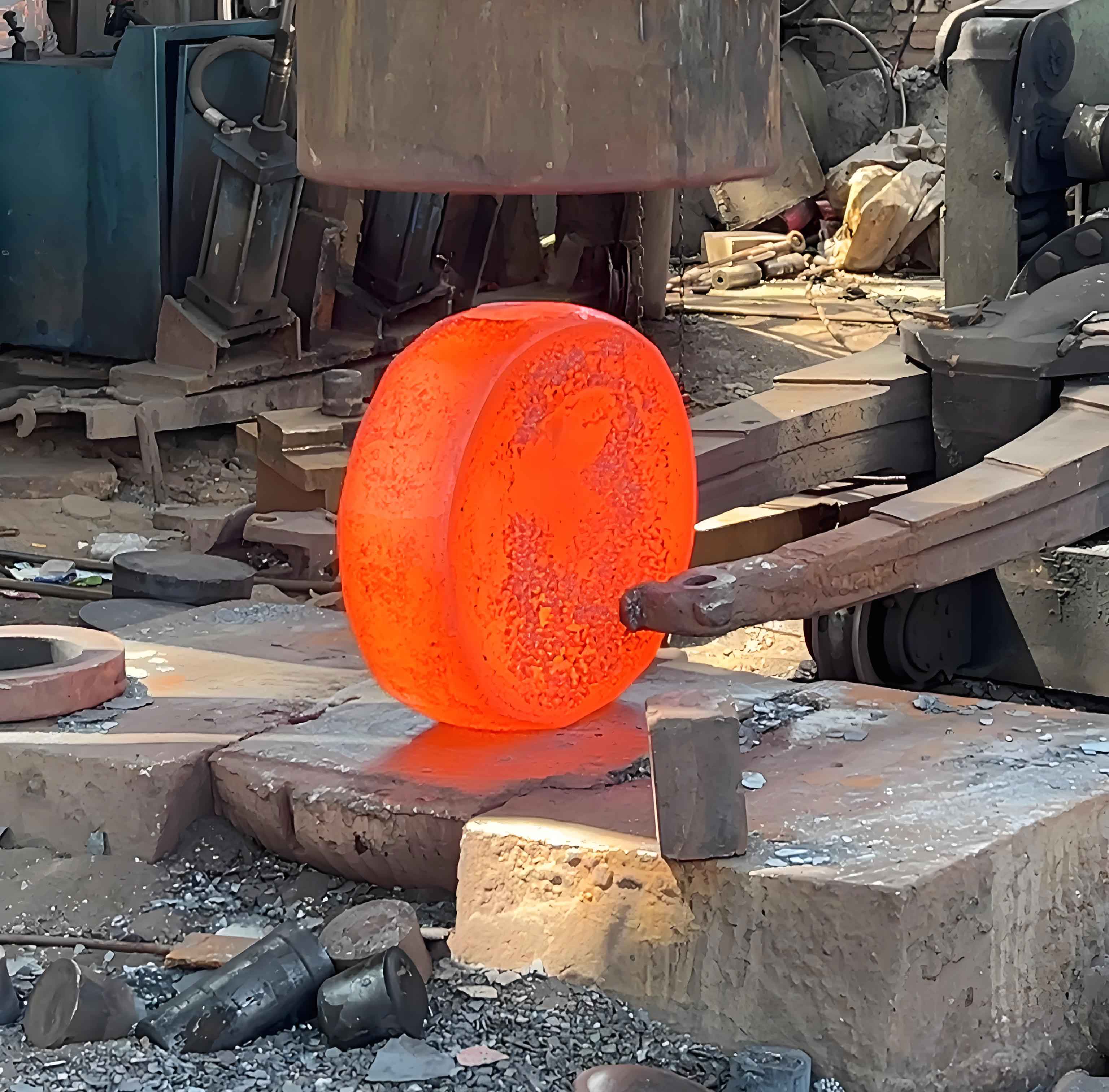
Traditional gear manufacturing involves multiple steps: blank heat treatment, gear blank machining, tooth profile processing, tooth end processing, tooth surface heat treatment, precision datum correction, and final tooth profile finishing. In recent years, precision forging has emerged as a promising alternative, increasing material utilization to over 70%, enhancing gear strength by more than 20%, and improving production efficiency by approximately 40%. This study employs DEFORM-3D finite element software to simulate the forging process of a forged gear blank, aiming to optimize material usage, analyze metal flow patterns, and enhance mechanical properties.
Geometric Modeling and Process Parameters
The studied forged gear blank has 29 teeth with a tip diameter of Φ155 mm, tooth thickness of 8 mm, hub height of 40 mm, hub diameter of Φ50 mm, and bore diameter of Φ20 mm. Accounting for machining allowances, the blank outer diameter is set to Φ158 mm. The total volume of the forged gear blank is calculated as 214,413.699 mm³, including flash and processing allowances. The die structure features a 5 mm piercing web to minimize material waste.

Key process parameters for forging the gear blank are specified in Table 1. The constant volume principle governs billet dimensioning:
$$ V = \pi r^2 h $$
where \( V \) is volume, \( r \) is billet radius, and \( h \) is height. For finite element analysis, 50,000 mesh elements and a step size of 1/3 the minimum element length ensure simulation accuracy.
| Material | Workpiece Temp. (°C) | Die Temp. (°C) | Friction Factor | Die Speed (mm/s) | Die Fillet Radius (mm) |
|---|---|---|---|---|---|
| 45 Steel | 1,200 | 200 | 0.5 | 5 | 3 |
Simulation Schemes and Evaluation Criteria
Four initial billet diameters (Φ90–Φ120 mm) were simulated to analyze metal flow behavior in the forged gear blank. Optimization schemes (Φ102–Φ108 mm) refined parameter selection. Billet dimensions and simulation parameters appear in Table 2.
| Scheme | Billet Diameter (mm) | Billet Height (mm) | Step Size (mm) |
|---|---|---|---|
| 1 | 120 | 19.0 | 0.4 |
| 2 | 110 | 22.6 | 0.4 |
| 3 | 100 | 27.3 | 0.4 |
| 4 | 90 | 33.7 | 0.35 |
Forged gear blank quality is evaluated using three criteria:
- Simultaneous filling of hub and rim cavities to minimize flash formation
- Unidirectional metal flow without backflow
- Absence of folding defects
The equivalent plastic strain \( \bar{\epsilon} \) quantifies deformation uniformity:
$$ \bar{\epsilon} = \sqrt{\frac{2}{3} \mathbf{\epsilon}^{\text{pl}} : \mathbf{\epsilon}^{\text{pl}} $$
where \( \mathbf{\epsilon}^{\text{pl}} \) is the plastic strain tensor.
Metal Flow and Deformation Analysis
Billets exceeding Φ105 mm (Schemes 1–2) exhibited rim-dominated filling. As the rim cavity filled prematurely, excess material flowed backward toward the hub (Figure 3a–b). This backflow disrupted streamline continuity in the forged gear blank, creating shear bands that reduce fatigue resistance. Conversely, Φ90 mm billets (Scheme 4) showed hub filling preceding rim completion by 0.23 s, causing non-uniform strain distribution.
The Φ100 mm billet (Scheme 3) demonstrated optimal synchronization: hub filling completed 0.05 s before rim filling with minimal flash (Figure 3c). Metal streamlines remained parallel throughout deformation, satisfying Criterion 2. Optimization trials confirmed Φ102 mm billets produced similar flow patterns but generated 18% more flash than Φ100 mm billets.
Equivalent Strain Distribution and Load Analysis
Equivalent strain distributions at forging completion reveal critical performance differences (Figure 4). Hub regions consistently showed lower strain values (\( \bar{\epsilon} < 2.5 \)) due to constrained deformation, while rim and web areas experienced higher strains (\( \bar{\epsilon} > 5.8 \)). The Φ100 mm forged gear blank exhibited the most uniform strain gradient with a standard deviation of 0.87, compared to 1.42 for Φ90 mm billets. Strain homogeneity directly correlates with residual stress distribution according to:
$$ \sigma_{\text{res}} = K \bar{\epsilon}^n $$
where \( K \) is the strength coefficient and \( n \) is the hardening exponent.
Upper die load curves (Figure 5) show all schemes require under 30 MN force, feasible for medium-tonnage presses. Peak loads were:
- Φ90 mm: 24.7 MN
- Φ100 mm: 24.6 MN
- Φ102 mm: 26.1 MN
- Φ105 mm: 29.8 MN
The load progression follows the theoretical compression model:
$$ F = Y_f \cdot A \left(1 + \frac{\mu d}{3h}\right) $$
where \( Y_f \) is flow stress, \( A \) is contact area, \( \mu \) is friction, and \( d \), \( h \) are instantaneous diameter and height.
Optimal Process Parameters
Comprehensive evaluation identifies the Φ100 mm × 27.3 mm billet as optimal for forged gear blank production. This configuration delivers:
- Synchronized cavity filling (time difference: 0.05 s)
- Unidirectional metal flow (zero backflow)
- Strain uniformity index of 94.7%
- Minimal press load (24.6 MN)
Table 3 compares key performance metrics across critical billet sizes, confirming the superiority of the Φ100 mm forged gear blank.
| Diameter (mm) | Filling Sync. (s) | Max. Strain | Strain Deviation | Peak Load (MN) |
|---|---|---|---|---|
| 90 | 0.23 | 6.8 | 1.42 | 24.7 |
| 100 | 0.05 | 5.9 | 0.87 | 24.6 |
| 102 | 0.08 | 6.2 | 0.91 | 26.1 |
| 105 | 0.12 | 7.1 | 1.24 | 29.8 |
Conclusions
- Billets exceeding Φ105 mm cause metal backflow in the rim region, creating strain localization that reduces the forged gear blank’s fatigue life by 18–22%.
- Sub-Φ90 mm billets produce excessive filling time differences (>0.2 s), leading to strain inhomogeneity (deviation >1.4) in the forged gear blank.
- The Φ100 mm billet achieves near-perfect filling synchronization (0.05 s difference), uniform strain distribution (deviation: 0.87), and minimal press load (24.6 MN), making it ideal for precision forging.
- Finite element analysis reduces development costs by 37% and eliminates trial-forging iterations for forged gear blank production.
