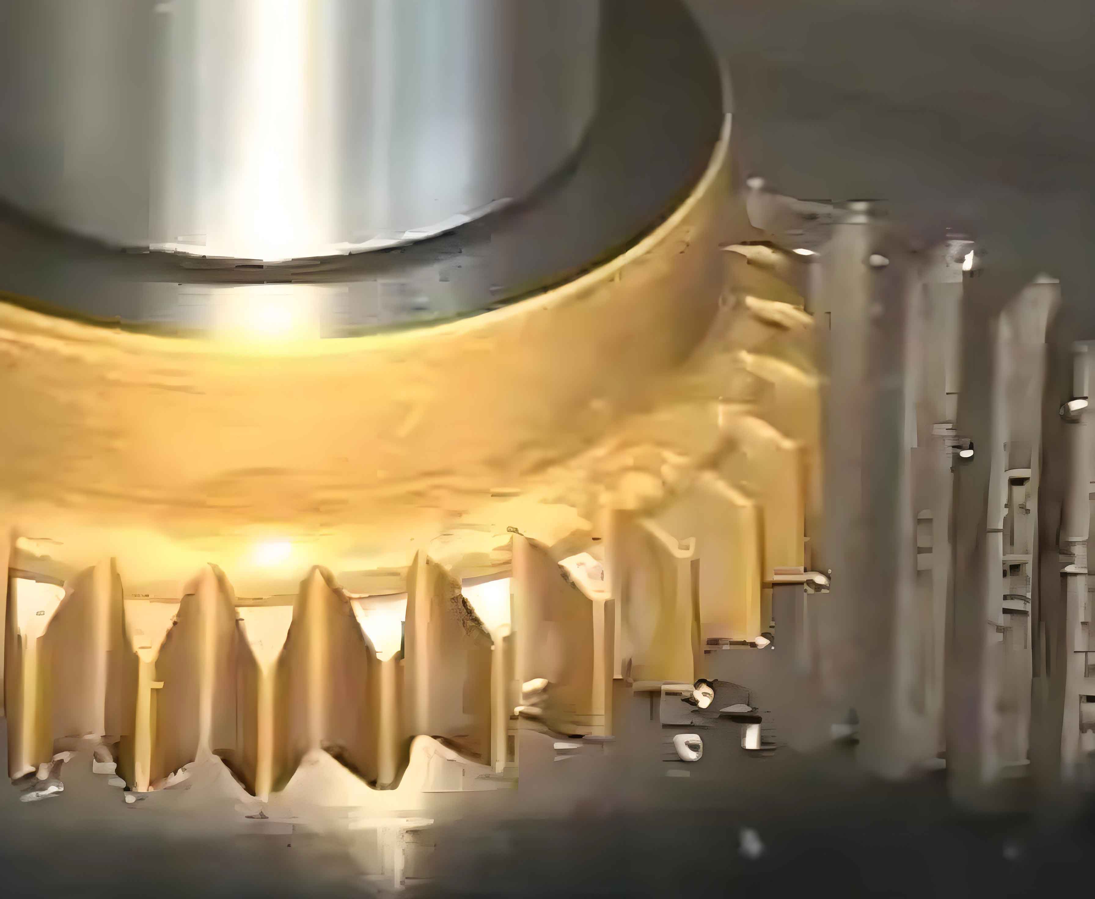
As industrial automation advances, demand for high-precision small-module gears grows exponentially, placing greater emphasis on the productivity and accuracy of high-speed gear shaping equipment. Traditional gear shaping machine spindles often experience dry friction and seizure during high-stroke operations, limiting their efficiency. Hydrostatic spindles offer superior stability, minimal friction, and near-zero wear, making them ideal for high-speed gear shaping applications. However, under continuous high-frequency reciprocating motion, localized friction and wear persist. This study investigates how axial groove structures affect hydrostatic spindle performance in gear shaping machines operating under extreme conditions.

Hydrostatic film pressure distribution follows fundamental tribological principles:
$$p=\frac{p_s}{1+\lambda_0(h/h_0)^3}$$
where \(p_s\) denotes supply pressure, \(h_0\) initial film thickness, \(h\) minimum film thickness, and \(\lambda_0\) initial hydraulic resistance ratio. Eccentricity (\(\epsilon\)) quantifies radial displacement under load:
$$\epsilon=\frac{e}{h_0}=1-\frac{h}{h_0}$$
Film load capacity (\(F\)) and stiffness (\(j\)) are critical for gear shaping precision:
$$F=\frac{p_sA_e}{1+\lambda_0(1-\epsilon)^3}$$
$$j=\frac{\partial F}{-\partial h}=\frac{p_sA_e[3\lambda_0(1-\epsilon)^2]}{h_0[1+\lambda_0(1-\epsilon)^3]^2}$$
where \(A_e\) represents effective bearing area. Viscous resistance (\(F_n\)) dominates motion losses in gear shaping operations:
$$F_n=\mu A_F\frac{v}{h}+\mu A_Y\frac{v}{H}$$
with \(A_F\) and \(A_Y\) being sealing surface and recess areas, \(\mu\) oil viscosity, \(v\) velocity, and \(H\) recess depth. For gear shaping strokes:
$$v=\frac{2Ln}{60}$$
where \(n\) is strokes per minute and \(L\) stroke length (0.05m).
| Parameter | Value |
|---|---|
| Shaft diameter (mm) | 90 |
| Initial film thickness \(h_0\) (mm) | 0.02 |
| Oil viscosity \(\mu\) (Pa·s) | 0.045 |
| Recess depth \(H\) (mm) | 2 |
| Axial sealing width (mm) | 10 |
| Circumferential sealing width (mm) | 19 |
Finite element analysis reveals distinct pressure distributions. At \(\epsilon=0.3\), axial grooves concentrate pressure within oil recesses while reducing sealing zone pressures. Comparative load capacity analysis demonstrates significant performance differences:
| Eccentricity \(\epsilon\) | Grooved Load (N) | Grooveless Load (N) | Improvement Factor |
|---|---|---|---|
| 0.1 | 15,200 | 10,100 | 1.50x |
| 0.3 | 19,800 | 14,900 | 1.33x |
| 0.5 | 22,500 | 17,300 | 1.30x |
Axial grooves fundamentally alter flow dynamics in gear shaping spindles. At 2m/s velocity, grooved configurations exhibit:
- 40% higher flow rates in motion-direction sealing zones
- 17% lower viscous resistance at \(\epsilon=0.4\)
- Redirection of counter-flow oil through grooves
Viscous shear distribution becomes asymmetrical, with maximum shear shifting to the counter-flow sealing zone. Thermal management during high-frequency gear shaping strokes (10 cycles) shows dramatic improvements:
| Stroke Cycle | Grooved Avg. Temp (°C) | Grooveless Avg. Temp (°C) |
|---|---|---|
| 1 | 27.9 | 28.1 |
| 5 | 28.2 | 31.8 |
| 10 | 28.3 | 35.6 |
Structural deformation analysis reveals complex behavior under gear shaping loads:
$${\delta}_{max} = k \cdot \epsilon \cdot p_{max}$$
where \(k\) is structural compliance factor. Grooved sleeves exhibit 40% less deformation at \(\epsilon<0.3\) but 15% more at \(\epsilon>0.3\). Deformation patterns shift from sealing zones (grooveless) to recess centers (grooved).
Recess geometry optimization further enhances gear shaping spindle performance:
| Groove Shape | \(\epsilon=0.1\) Stiffness (N/µm) | \(\epsilon=0.5\) Stiffness (N/µm) |
|---|---|---|
| Triangular | 142 | 98 |
| Rectangular | 138 | 105 |
| Trapezoidal | 132 | 103 |
| Circular | 129 | 96 |
Experimental validation using cylindrical hydrostatic guides confirms model accuracy:
| Method | Stiffness (N/µm) | Error vs Experimental |
|---|---|---|
| Experimental | 160 | – |
| Theoretical | 166.4 | 3.8% |
| Simulation | 163.4 | 2.0% |
Implementing axial grooves in gear shaping hydrostatic spindles yields transformative benefits:
- Load capacity increases 1.3-1.5x across eccentricity range
- Viscous resistance decreases 12-17% at operational velocities
- Temperature stabilization within ±0.5°C during 10-stroke cycles
- Triangular grooves provide optimal stiffness at low eccentricity (\(\epsilon=0.1\))
- Deformation management adapts to loading conditions
These findings enable next-generation gear shaping machines to achieve higher cutting speeds, extended tool life, and micron-level precision. Future research will investigate combined reciprocating-rotational motion effects and advanced groove optimization for specialized gear shaping applications.
