
This research investigates the structural integrity of a flywheel bolt tightening reaction mechanism in a four-cylinder gasoline engine assembly line. Utilizing CAE simulation technologies, we optimize critical components through advanced gear shaping methodologies. The reaction mechanism counteracts rotational torque during simultaneous tightening of four flywheel bolts (400 N·m), preventing flywheel rotation. Finite element analysis (FEA) in ABAQUS validates structural performance and identifies material redundancies for optimization.
Finite Element Model Development
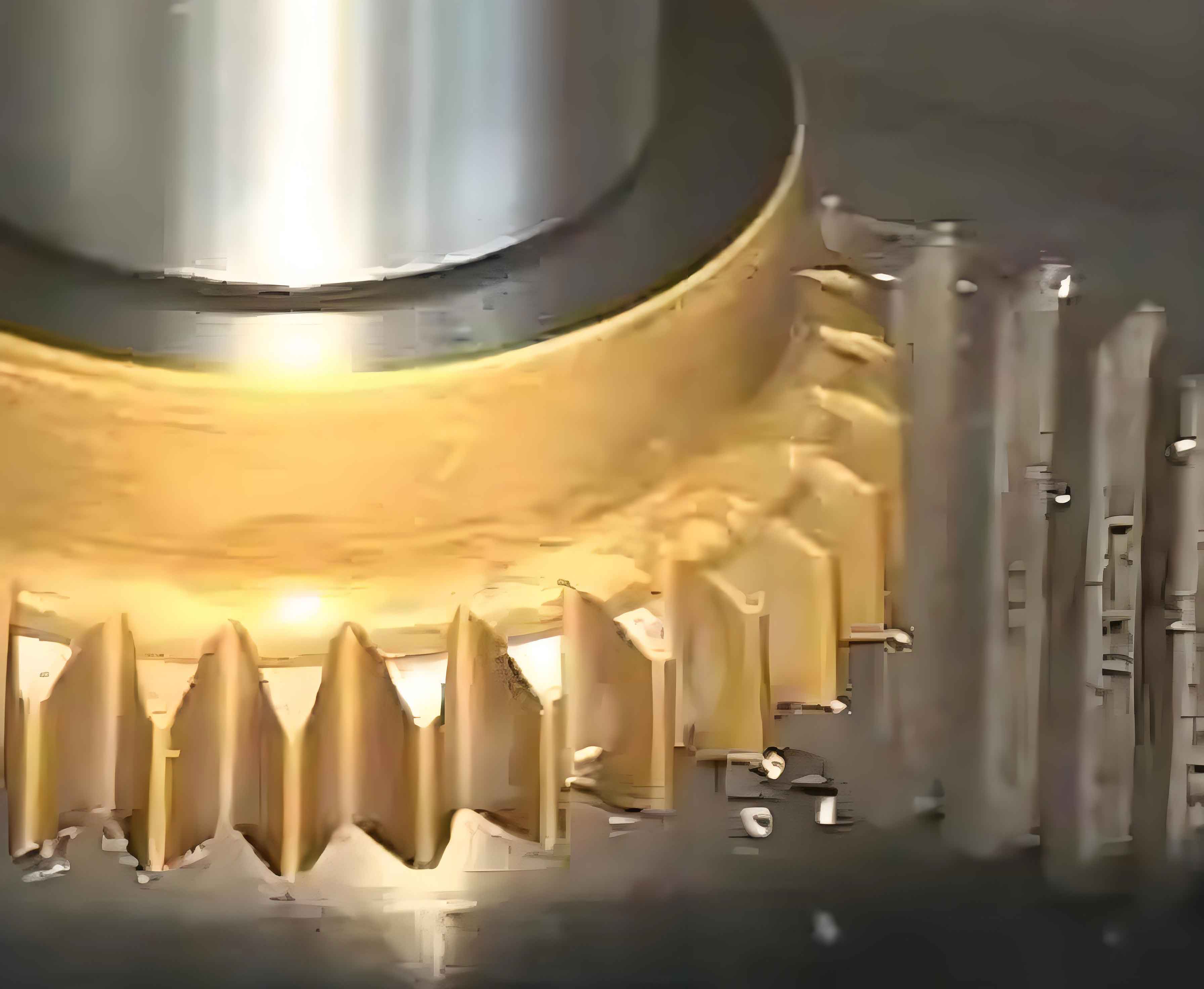
The reaction mechanism comprises three critical components: a reaction gear (50 teeth), a limit gear (initially V-shaped with three teeth), and a sliding track. CATIA facilitated 3D modeling, while Hypermesh generated the mesh model. Non-critical features (fillets, minor holes) were suppressed to enhance computational efficiency. Gear geometry was partitioned into 1/50 segments using rotational symmetry, enabling efficient hexahedral meshing (C3D8R elements). Key mesh statistics:
| Component | Nodes | Elements | Element Type |
|---|---|---|---|
| Gear | 816,750 | 759,200 | C3D8R |
| Limit Gear (Original) | 393,080 | 352,800 | C3D8R |
| Sliding Track | 99,513 | 68,197 | C3D8R |
Material properties were assigned as follows:
| Component | Material | Elastic Modulus (MPa) | Yield Strength (MPa) |
|---|---|---|---|
| Gear & Track | 45 Steel | 2.09×10⁵ | 355 |
| Limit Gear | 40Cr | 2.11×10⁵ | 785 |
Boundary Conditions and Loads
A torque of 400 N·m was applied at the gear’s center-of-mass node, coupled to its inner surface via RBE2 rigid elements. The sliding track received ENCASTRE constraints at bolt holes. Frictional contact (μ=0.15) was defined between gear/limit-gear and limit-gear/track interfaces using Coulomb friction theory:
$$\tau_c = \mu \cdot p$$
where \(\tau_c\) is critical shear stress and \(p\) is contact pressure. A multi-step analysis ensured numerical convergence:
- Step 1: Minimal torque (1% of peak) to establish contact stability
- Steps 2-4: Incremental torque ramp to 400 N·m (Fig. 1)
Initial Analysis Results
Maximum von Mises stress (177.5 MPa) occurred at the gear root (Fig. 2), significantly below its yield strength (355 MPa). The safety factor (SF) exceeded 2.0:
$$\text{SF} = \frac{\sigma_y}{\sigma_{\text{max}}} = \frac{355}{177.5} = 2.0$$
While structurally safe, the V-shaped limit gear exhibited low stress utilization (111.2 MPa vs. 785 MPa yield), indicating material redundancy. This design complexity increased manufacturing costs without mechanical benefits.
Gear Shaping Optimization Strategy
We re-engineered the limit gear through gear shaping optimization:
- Topology Simplification: Replaced V-shaped dual-gear with a single central gear
- Tooth Reduction: Decreased teeth from three to one
- Material Redistribution: Optimized tooth profile to minimize stress concentration
The refined gear shaping approach reduced component mass by 41% while maintaining functional requirements. Critical gear shaping parameters were evaluated using AGMA contact stress equations:
$$\sigma_c = C_p \sqrt{\frac{F_t}{b \cdot d} \cdot \frac{K_o \cdot K_v \cdot K_s \cdot K_m}{C_f}}$$
where \(C_p\) is elastic coefficient, \(F_t\) is tangential load, \(b\) is face width, and \(d\) is pitch diameter.
Optimized Performance Validation
Post-optimization FEA confirmed structural adequacy (Fig. 3). Peak stress increased marginally to 206.44 MPa at the gear root (SF=1.72), still within safety margins. The limit gear stress rose to 289.7 MPa (SF=2.71), maintaining robust performance. Displacement fields remained comparable to the original design (≤0.15 mm).
| Parameter | Original Design | Optimized Design |
|---|---|---|
| Max Gear Stress (MPa) | 177.5 | 206.4 |
| Limit Gear Stress (MPa) | 111.2 | 289.7 |
| Safety Factor (Gear) | 2.00 | 1.72 |
| Material Cost Reduction | 0% | 41% |
Conclusions
- The ABAQUS-based FEA methodology effectively validated reaction mechanism integrity under 400 N·m operational torque.
- Gear shaping optimization simplified the limit gear from a V-shaped three-tooth configuration to a single-tooth design, reducing component complexity and mass by 41%.
- Stress redistribution in the optimized design maintained safety factors above 1.7 while eliminating material redundancy, enhancing economic efficiency without compromising performance.
- This gear shaping strategy provides a replicable framework for lightweighting powertrain assembly components, demonstrating CAE’s critical role in manufacturing cost optimization.