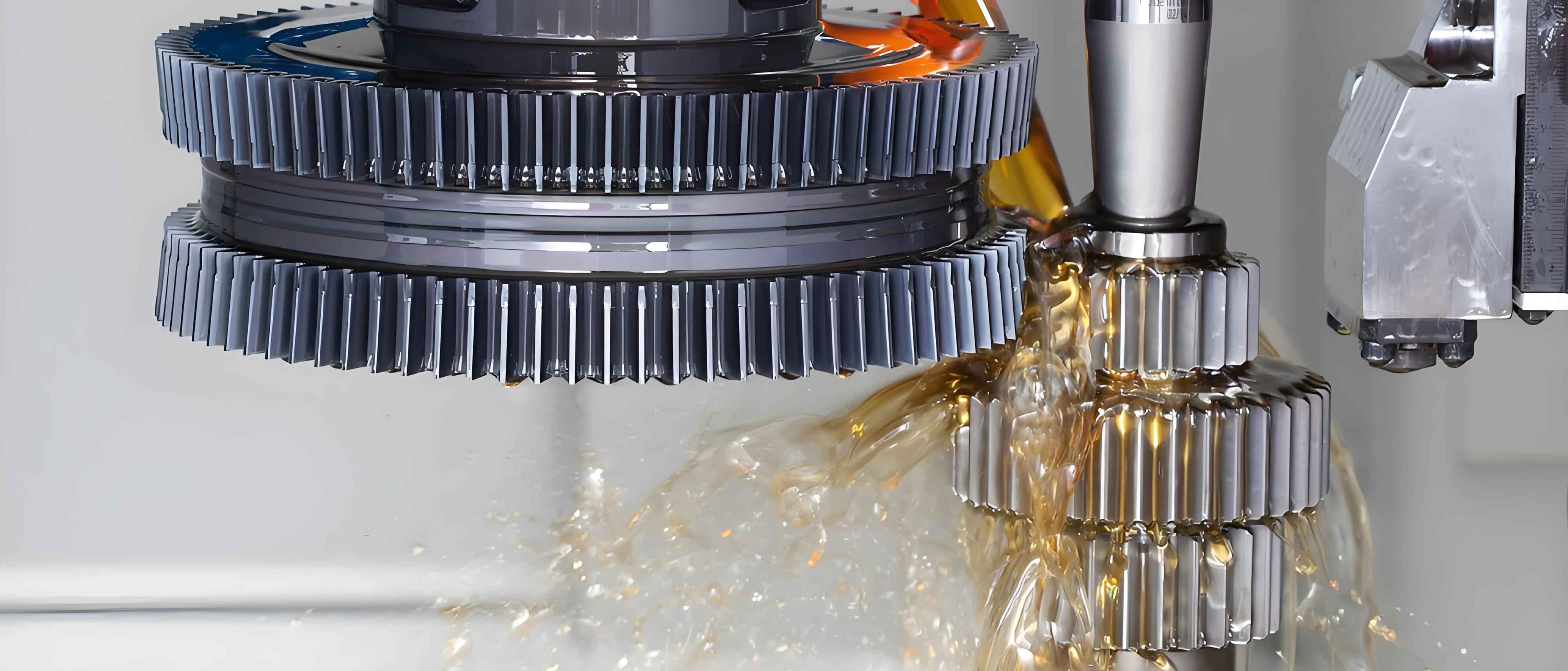
Spherical gears represent a breakthrough in transmission mechanisms, offering two rotational degrees of freedom while maintaining precise fixed transmission ratios. Their compact design enables transformative applications in bionic joints, robotic articulations, underwater thrust vectoring systems, and legged-wheel hybrid platforms. Among spherical gear variants, ring-involute tooth spherical gears (RITSG) eliminate the inherent errors of discrete-tooth designs through continuous tooth distribution across the spherical surface. The manufacturing evolution of these components has progressed through several phases:

Casting Technologies
Early RITSG production employed sand-coated iron mold casting. This process involves pattern assembly, sand shooting through injection ports, curing, mold separation, and molten metal pouring. The workflow follows:
- Pattern and iron mold assembly
- Resin-coated sand injection and curing
- Mold separation and cavity formation
- Molten metal pouring (e.g., austempered ductile iron)
Key advantages include reduced machining allowances and improved metallurgical properties. However, limitations persist in dimensional accuracy control, where casting defects cause significant deviations from theoretical tooth profiles. The shrinkage porosity index $\eta_p$ quantifies this limitation:
$$ \eta_p = \frac{V_p}{V_g} \times 100\% $$
where $V_p$ represents pore volume and $V_g$ denotes gear volume. Typical $\eta_p$ values range 0.8-1.5%, directly impacting fatigue strength.
| Parameter | Traditional Casting | Sand-Coated Mold |
|---|---|---|
| Surface Roughness (Ra, μm) | 25-50 | 12.5-25 |
| Dimensional Tolerance (mm) | ±1.5 | ±0.8 |
| Shrinkage Porosity Rate | High | Moderate |
Form Machining Approaches
Profile copying techniques utilize form tools replicating the involute tooth space geometry. Two primary implementations exist:
1. Form Turning: The spherical blank rotates about its polar axis while a stationary non-rotating tool radially feeds according to the trajectory equation:
$$ r(\phi) = R \sqrt{1 – \cos^2\beta \sin^2\phi} $$
where $R$ is sphere radius, $\beta$ is cone angle, and $\phi$ is rotation angle.
2. Form Milling: The rotating cutter engages the rotating workpiece, with synchronized movements governed by:
$$ \begin{cases}
\omega_w = \frac{v_c}{d_m} \\
f_z = z \cdot f_t
\end{cases} $$
where $\omega_w$ is workpiece angular velocity, $v_c$ is cutting speed, $d_m$ is mean diameter, $f_z$ is feed per tooth, and $z$ is tooth count. This gear shaping method suffers from low productivity due to discontinuous cutting and inherent profile inaccuracies when approximating complex spherical surfaces with finite cutting points.
Generating/Gear Shaping Processes
True involute generation simulates rack-and-pinion kinematics through coordinated motions. The fundamental principle establishes continuous tangency between the imaginary generating rack and the spherical envelope surface. The kinematic chain requires:
- Pure rolling motion ($\omega_g \cdot r_p = v_r$) between gear blank and virtual rack
- Orbital revolution around the polar axis ($\omega_p$)
- Linear tool translation ($v_t$)
The resulting motion equations define the cutting path:
$$ \begin{bmatrix} x \\ y \\ z \end{bmatrix} = R_z(\theta) \cdot R_y(\phi) \cdot \begin{bmatrix} r_b (\cos\sigma + \sigma \sin\sigma) \\ r_b (\sin\sigma – \sigma \cos\sigma) \\ 0 \end{bmatrix} + \begin{bmatrix} 0 \\ 0 \\ v_t t \end{bmatrix} $$
where $r_b$ is base radius, $\sigma$ is involute roll angle, $\theta$ and $\phi$ are rotation angles.
Advanced implementations employ CNC-controlled grinding systems. A disk-shaped grinding wheel profiles the tooth space through synchronized 5-axis movements. The contact kinematics follow:
$$ \overrightarrow{V_c} = (\overrightarrow{\omega_g} \times \overrightarrow{r_c}) – (\overrightarrow{\omega_w} \times \overrightarrow{r_c}) $$
where $\overrightarrow{V_c}$ is relative velocity at contact point, $\overrightarrow{\omega_g}$ and $\overrightarrow{\omega_w}$ are grinding wheel and workpiece angular velocities, and $\overrightarrow{r_c}$ is contact vector. This gear shaping approach achieves surface finishes of Ra 0.4-0.8 μm and profile accuracy grades AGMA 8-9.
| Manufacturing Method | Accuracy (AGMA) | Surface Roughness (Ra, μm) | Production Rate |
|---|---|---|---|
| Casting | 12-14 | 12.5-25 | High |
| Form Milling | 10-12 | 3.2-6.3 | Low |
| Gear Shaping (Grinding) | 8-9 | 0.4-0.8 | Medium |
Advanced Manufacturing Frontiers
Five-Axis CNC Machining: Contemporary solutions integrate tilt-rotary tables with helical tool paths. The tool orientation vector $\hat{T}$ follows the spherical surface normal $\hat{N}$:
$$ \hat{T} = \frac{\nabla F(x,y,z)}{||\nabla F(x,y,z)||} $$
where $F(x,y,z) = x^2 + y^2 + z^2 – R^2$ defines the spherical surface. Toolpath optimization minimizes kinematic errors through jerk-controlled motion profiles:
$$ J(t) = \frac{d^3P}{dt^3} < J_{\max} $$
This enables AGMA 6-7 accuracy with Ra 0.8-1.6 μm surfaces in hardened steels (55-62 HRC).
Additive Manufacturing: Metal powder bed fusion (PBF) builds RITSG layer-by-layer. Critical process parameters include:
- Laser power: $P_L = \frac{\kappa \cdot \Delta T \cdot v_s \cdot d_s \cdot \rho}{4\alpha}$
- Hatch spacing: $h_s \leq 0.8 \cdot \text{spot diameter}$
- Layer thickness: 20-40 μm
where $\kappa$ is thermal conductivity, $\Delta T$ is melting range, $v_s$ is scan speed, $d_s$ is spot size, $\rho$ is density, and $\alpha$ is absorptivity. Post-processing through hot isostatic pressing (HIP) achieves 99.5%+ density and tooth bending strength comparable to wrought materials. This gear shaping approach eliminates tooling constraints for customized geometries.
Critical Technology Gaps
Despite advancements, key challenges persist in spherical gear shaping:
- Metrology: In-situ profile measurement requires solutions for spherical coordinate verification with uncertainty < 5 μm
- Tooth Flank Modification: Topology optimization algorithms for spherical crowning remain underdeveloped
- Residual Stress Management: Thermal compensation models for AM distortions need refinement
- High-Performance Cutting Tools: Custom tool geometries for spherical gear shaping require PVD-coated carbide substrates
The path forward involves hybrid manufacturing strategies combining additive deposition for near-net shaping with precision finishing through advanced gear shaping techniques. Continued innovation in these domains will unlock the full potential of spherical gears across robotics, aerospace, and automotive applications.
