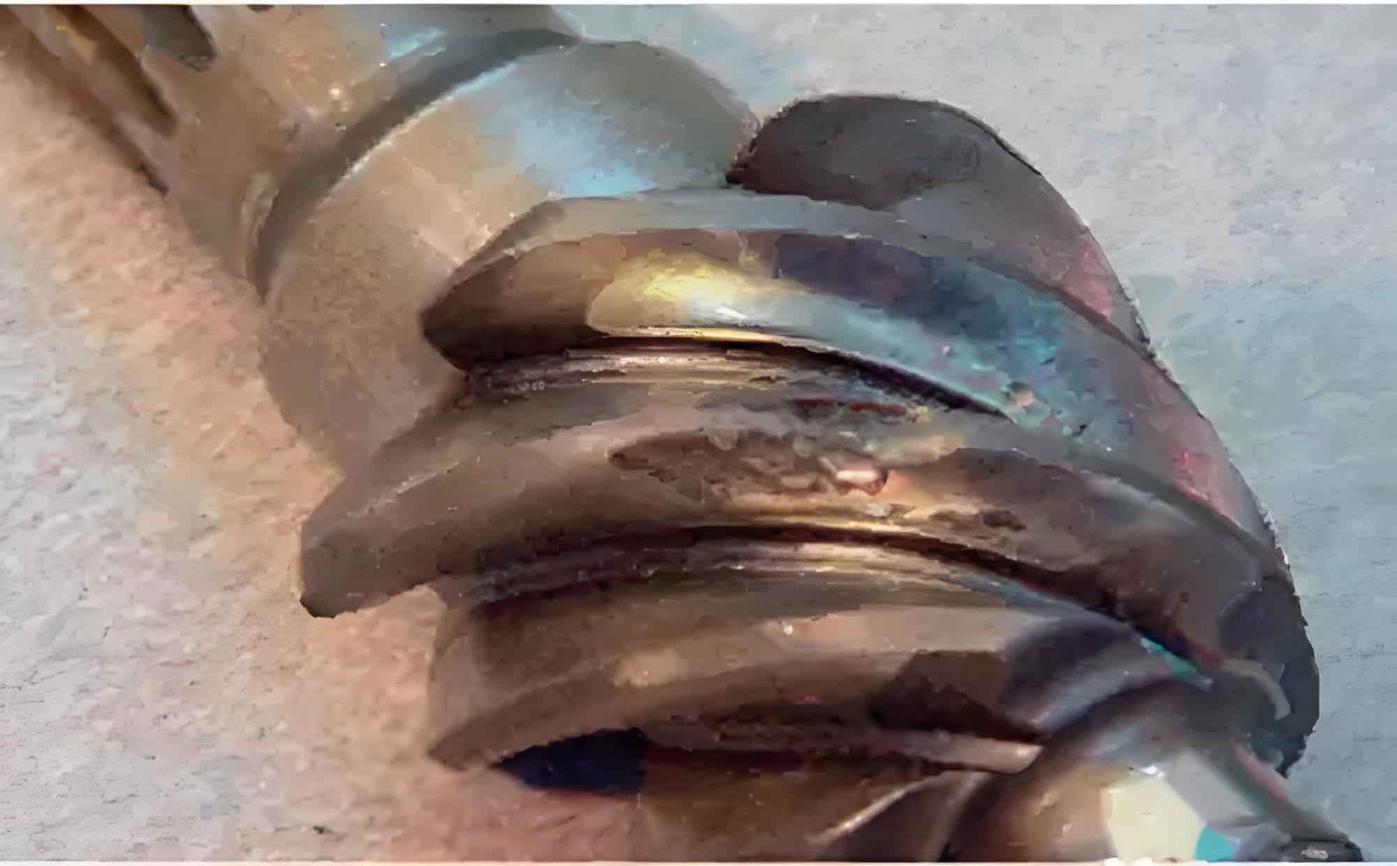
In heavy-duty truck transmissions, gear failure remains a critical concern, manifesting as pitting, scuffing, wear, and tooth breakage due to uneven contact stress distribution. These failures accelerate component degradation and compromise transmission reliability. Traditional helix angle modifications often fail to resolve persistent edge-loading (“offset load”) issues. This study introduces a targeted helix angle modification methodology to optimize contact patterns, enhance load distribution, and mitigate gear failure risks. Using a 12-speed transmission as a case study, we combine finite element analysis (FEA) with physical testing to validate the approach.
1. Helix Angle Modification Methodology
Helix angle modification adjusts the nominal helix angle (\(\beta\)) to counteract manufacturing deviations, assembly misalignments, and deflections. The modification slope (\(\Delta x\)) directly relates to the helix angle adjustment (\(\Delta\beta\)) across the face width (\(B\)):
$$\Delta\beta = \arctan\left(\tan\beta + \frac{\Delta x}{B}\right) – \beta$$
where \(\Delta x > 0\) increases \(\beta\) and \(\Delta x < 0\) decreases \(\beta\). Consistency in base pitch (\(P_b\)) before and after modification is critical. The relationship between transverse pressure angles (\(\alpha_t\)) and helix angles satisfies:
$$P_{bt1} = P_{bt2} \implies \frac{\cos\alpha_{t1}}{\cos\beta_1} = \frac{\cos\alpha_{t2}}{\cos\beta_2}$$
Solving for the modified normal pressure angle (\(\alpha_{n2}\)):
$$\alpha_{n2} = \arctan\left(\tan\alpha_{t2} \cdot \cos\beta_2\right)$$
where \(\beta_2 = \beta_1 + \Delta\beta\).
Directionality of Modification: The correction direction depends on gear handedness and contact offset (Figure 1):
| Handedness | Contact Bias | Required \(\Delta\beta\) Adjustment |
|---|---|---|
| Right-Hand Drive Gear | Left Edge | Increase \(\beta\) |
| Right-Hand Drive Gear | Right Edge | Decrease \(\beta\) |
| Left-Hand Drive Gear | Left Edge | Decrease \(\beta\) |
| Left-Hand Drive Gear | Right Edge | Increase \(\beta\) |

Optimization Workflow: The iterative process involves:
- Baseline contact pattern assessment
- \(\Delta\beta\) calculation and gear parameter adjustment
- FEA simulation and physical validation
- Re-iteration if performance targets are unmet
2. Contact Pattern Simulation and Experimental Validation
2.1 Simulation Model: A 12-speed transmission’s secondary shaft drive gear pair (1st gear) was analyzed. The drive gear (right-handed) exhibited severe right-edge bias, necessitating \(\Delta x = -30 \mu m\) modification. Key parameters include:
| Original Parameters | Modified Parameters | ||
|---|---|---|---|
| Teeth (\(z\)) | 36 | Teeth (\(z\)) | 36 |
| Module (\(m_n\)) | 3.4 mm | Module (\(m_n\)) | 3.4 mm |
| \(\beta\) | 22.5° | \(\Delta x\) | -30 μm |
| \(\alpha_n\) | 20° | \(\Delta\beta\) | -0.0386° |
| Face Width (\(B\)) | 38 mm | \(\beta_2\) | 22.4614° |
| Handedness | Right | \(\alpha_{n2}\) | 19.9676° |
FEA results using Romax Designer showed:
- Unmodified Gear: Stress concentration at the right edge (peak stress: 1,580 MPa), indicating high risk of localized gear failure.
- Modified Gear: Uniform stress distribution (peak stress: 1,220 MPa) with centered contact, reducing edge-loading and subsequent gear failure.
2.2 Contact Pattern Testing: Physical tests with \(\Delta x = \{-30, -20, -10, 10\} \mu m\) confirmed FEA predictions. Before modification, Gear 1 (drive) and Gears 2/3 (driven) exhibited pronounced right-edge bias. Post-modification (\(\Delta x = -30 \mu m\)):
- Contact patches shifted left by 5–10 mm and centralized
- Contact area increased by ~35%
- Edge-loading eliminated
2.3 Noise Testing: Noise spectra across gears showed negligible differences post-modification. Peak noise levels remained within ISO 362-1 standards, confirming that helix angle adjustments do not exacerbate acoustic emissions or induce new gear failure modes.
2.4 Fatigue Testing: The modified gear pair underwent 50 duty cycles (equivalent to 500,000 km):
- 20 Cycles: No pitting or scuffing; contact patterns aligned with bench tests.
- 50 Cycles: Uniform wear distribution without edge deterioration, satisfying ISO 6336 fatigue limits and preventing gear failure initiation.
3. Conclusions
Helix angle modification effectively mitigates contact bias in heavy-duty transmission gears:
- Direction-specific \(\Delta\beta\) adjustments (based on handedness and bias direction) centralize contact patterns, minimizing stress peaks that cause gear failure.
- FEA-guided optimization (\(\Delta x = -30 \mu m\)) reduced peak contact stress by 23% and eliminated edge-loading.
- Experimental validation confirmed centered contact patches, unchanged noise emissions, and fatigue performance exceeding industry standards, preventing premature gear failure.
This methodology provides a robust framework for correcting offset loads, extending gear service life, and enhancing transmission reliability. Future work will explore combined helix angle and profile modifications for complex gear failure scenarios.
