
With the rapid development of new energy vehicles (NEVs), transmission gear order noise previously masked by internal combustion engines becomes prominent. Traditional noise mitigation conflicts with compressed project timelines and limited resources. This article presents a “DNA” design methodology addressing gear failure risks by embedding noise, vibration, and harshness (NVH) considerations at the initial design phase. This approach enhances first-pass success rates, reduces development cycles, and minimizes validation costs.
1. Concept Design Stage
Gears are critical transmission components requiring rigorous design for functionality, durability, and NVH performance. The DNA approach mandates holistic evaluation through a decision matrix:
| Indicator | Weight | Scheme 1 (Baseline) | Scheme 2 | Scheme 3 |
|---|---|---|---|---|
| Benchmarking | 5 | 5 | 7 | 3 |
| Performance | 8 | 5 | 9 | 7 |
| Weight | 5 | 5 | 3 | 7 |
| Reliability | 8 | 5 | 7 | 9 |
| Interfacing Changes | 8 | 5 | 3 | 7 |
| Manufacturability | 5 | 5 | 7 | 3 |
| Platform Commonality | 5 | 5 | 3 | 7 |
| Cost | 8 | 5 | 7 | 3 |
| Timeline | 5 | 5 | 3 | 7 |
| Total Score | – | 285 | 298 | 287 |
1.1 Sources of Gear Order Noise
Gear order noise originates from meshing impacts. Vibration propagates from gear teeth to shafts, bearings, and housings, radiating audible noise. Preventing gear failure requires addressing three key areas:
1.2 Meshing Frequency Optimization
Excessive meshing frequency causes whining noise. Mitigation strategies:
- Limit input-stage gear teeth count (avoiding <17 teeth to prevent undercutting)
- Ensure >7% separation between gear mesh orders and motor pole/slot harmonics
Order separation formula for resonance avoidance:
$$ \Delta O = \left| O_{\text{gear}} – O_{\text{motor}} \right| \geq 0.07 \times O_{\text{motor}} $$
1.3 Meshing Impact Energy Reduction
Impact energy governs vibration amplitude:
$$ E = \frac{1}{2} m v^2 $$
$$ v = a \times \Delta t $$
Where \(m\) = effective tooth mass, \(v\) = relative velocity, \(a\) = acceleration, and \(\Delta t\) = backlash traversal time. Countermeasures:
- Minimize backlash to reduce \(\Delta t\)
- Optimize transverse (\(\epsilon_\alpha\)) and overlap (\(\epsilon_\beta\)) contact ratios
Total contact ratio constraint to prevent tooth tip fracture:
$$ \epsilon_\gamma = \epsilon_\alpha + \epsilon_\beta \leq 3.2 $$
1.4 Support Structure Design
Misalignment (axial/radial/angular) induces backlash variations and contact ratio fluctuations, accelerating gear failure. Design rules:
- Axial retention: ≥1.5mm meshing margin
- Radial alignment: Maximize coaxiality
- Stiffness enhancement: Minimize overhung spans, specify high-strength materials
1.5 Manufacturing Precision
Process-induced errors (single pitch deviation, accumulated pitch error) cause backlash inconsistencies. High-speed applications (≤16,000 rpm) require:
- Grinding/honing post heat-treatment
- Nitriding for internal gears to minimize distortion
- Surface roughness ≤ 0.4 μm Ra
2. Detailed Design Stage
System-level modeling (MASTA/Romax) evaluates transmission performance under operational loads. Key metrics include mesh misalignment and transmission error.
2.1 Macro-Optimization
Mesh misalignment minimization focuses on:
- Gear web stiffness optimization
- Shaft deflection control via bearing preload
- Rigid housing connections
2.2 Micro-Optimization
Peak-to-peak transmission error (PPTE) predicts gear failure risks. Multi-condition simulations evaluate contact patterns under torque reversals:
| Operating Condition | Gear Pair | PPTE (μm) | Target (μm) |
|---|---|---|---|
| 30% Torque | High-Speed Stage | 0.1760 | <0.5 |
| Low-Speed Stage | 0.2136 | ||
| 60% Torque | High-Speed Stage | 0.0554 | |
| Low-Speed Stage | 0.1194 | ||
| 90% Torque | High-Speed Stage | 0.3597 | |
| Low-Speed Stage | 0.1707 |
Design of Experiments (DOE) optimizes micro-geometry modifications:
| Factor | Level 1 | Level 2 | Level 3 |
|---|---|---|---|
| Pinion Lead Crown (μm) | +Tol | Nominal | -Tol |
| Pinion Helix Modification | +Tol | Nominal | -Tol |
| Wheel Lead Crown (μm) | +Tol | Nominal | -Tol |
| Wheel Helix Modification | +Tol | Nominal | -Tol |
Effect analysis identifies sensitivity to tolerance variations, ensuring robustness against manufacturing-induced gear failure.
3. Design Verification
Prototype testing validates DNA design effectiveness:
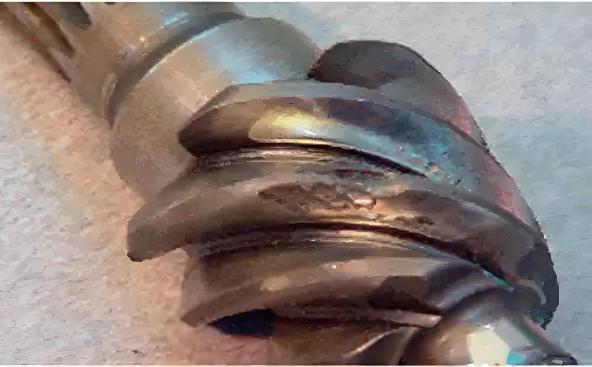
3.1 Durability and Surface Integrity
Post-endurance gear inspection confirms no pitting, spalling, or abnormal wear. Contact patterns align with simulations:
3.2 Order Noise Performance
Order slices exhibit >30 dB separation from broadband noise, confirming absence of tonal gear failure signatures.
3.3 Contact Pattern Validation
Physical contact patterns under loaded conditions correlate with simulation predictions, demonstrating uniform load distribution without edge loading.
4. Conclusion
The DNA design methodology eliminates late-stage NVH compromises by integrating gear failure prevention into initial system architecture. Key outcomes:
- 30% reduction in development cycles
- Near-elimination of prototype iteration costs
- Guaranteed NVH performance at SOP
This approach establishes a new paradigm for high-reliability transmission design in electrified powertrains.