
In this investigation, we examine a critical gear failure incident involving driving and driven gears from an aircraft engine’s N2 sensor system. During flight operations, the N2 speed indicator dropped to zero, triggering a single-engine shutdown. Post-landing inspection revealed metallic debris in the oil filter, with energy-dispersive spectroscopy (EDS) confirming low-alloy steel composition consistent with carbonitrided layers. Both gears, manufactured from 12Cr2Ni4A steel with surface carbonitriding, exhibited severe wear and partial tooth fractures. Our comprehensive analysis integrates macroscopic examination, scanning electron microscopy (SEM), EDS, metallography, and hardness testing to establish the root cause of this gear failure.
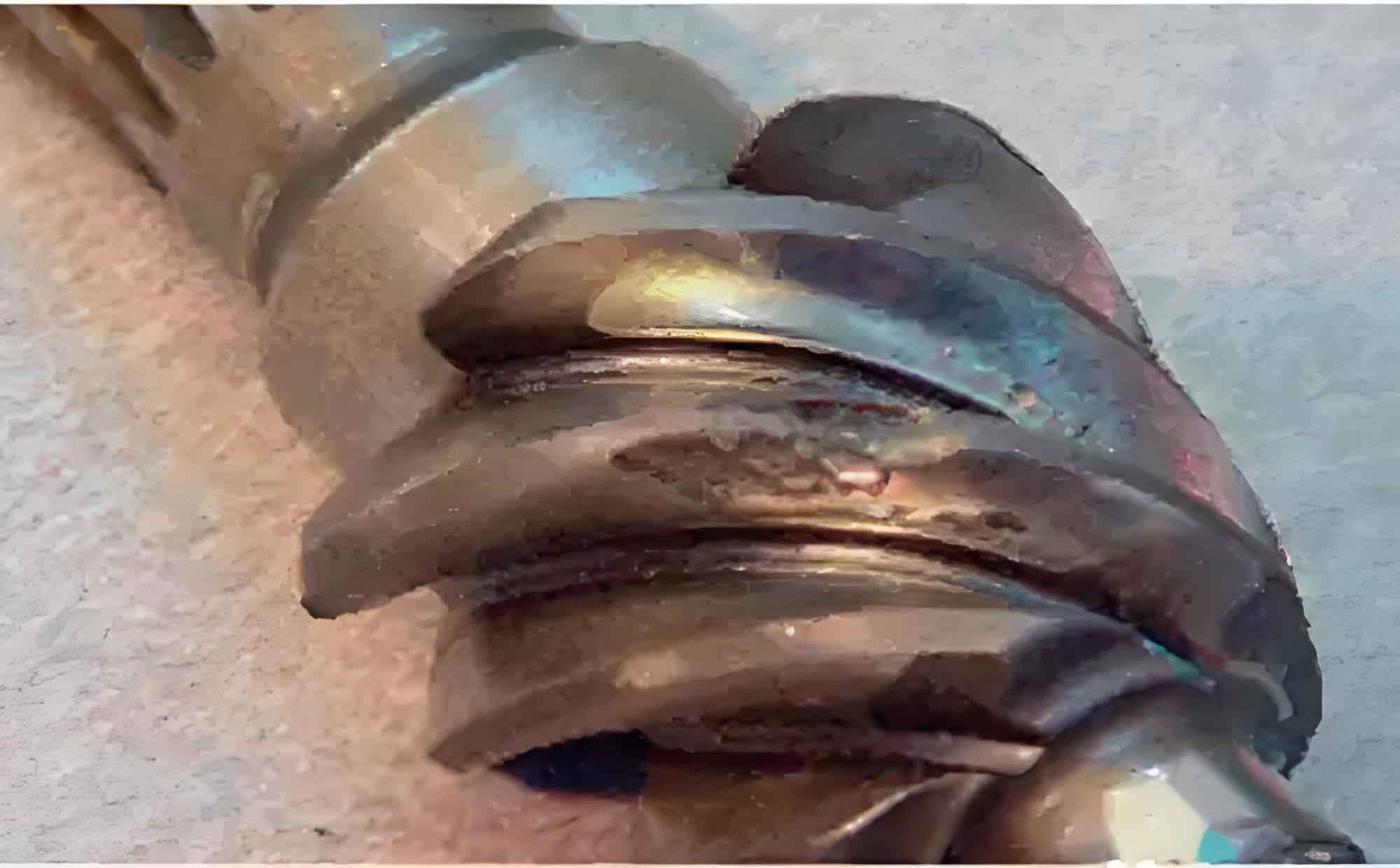
The driving gear (24 teeth) and driven gear (38 teeth) displayed catastrophic damage patterns. Macroscopic analysis showed uniform wear on the driving gear tooth crests (~0.5 mm depth) with five teeth fractured at the roots. The driven gear exhibited more severe gear failure characteristics: 33 teeth suffered crest spalling, while the remaining five showed minimal wear. Crucially, one driven gear tooth displayed classic fatigue progression marks, identified as the initiation point for subsequent gear failure. Contact marks at unusual positions indicated abnormal meshing between components.
SEM analysis of the fracture initiation site revealed distinct regions characteristic of fatigue-induced gear failure. The fracture origin appeared as a linear surface defect, indicative of high initial stress concentration. The propagation region covered approximately 85% of the fracture surface, displaying well-defined fatigue striations and beach marks described by:
$$\Delta K = Y \Delta \sigma \sqrt{\pi a}$$
where \(\Delta K\) is the stress intensity factor range, \(Y\) is the geometry factor, \(\Delta \sigma\) is the applied stress range, and \(a\) is the crack length. The final fracture zone exhibited intergranular morphology, occupying less than 15% of the total area, confirming low overload stresses. EDS analysis detected no contaminant elements at the origin site, as shown in Table 1.
| Cr | Fe | Ni |
|---|---|---|
| 1.30 | 97.29 | 1.41 |
Metallographic examination demonstrated proper material processing and heat treatment. Both gears exhibited consistent carbonitrided layers (0.15–0.19 mm for driven gear) with acceptable microstructure: surface regions contained retained austenite and acicular martensite, while core regions showed tempered martensite. Vickers microhardness measurements aligned with specification requirements, as summarized in Table 2. These results eliminate material defects or heat treatment errors as contributing factors in this gear failure event.
| Component | Measurement Points | Average | ||||
|---|---|---|---|---|---|---|
| Driven Gear | 429 | 437 | 440 | 438 | 435 | 436 |
| Driving Gear | 420 | 413 | 415 | 419 | 418 | 417 |
The gear failure mechanism is attributed to abnormal assembly-induced fatigue. Evidence includes unusual contact patterns at tooth roots and crests, indicating misalignment during operation. The driving gear, with smaller diameter and fewer teeth, experienced higher cyclic stresses according to:
$$\sigma_b = \frac{W_t}{F} \cdot \frac{K_m K_v}{m} \cdot Y$$
where \(\sigma_b\) is bending stress, \(W_t\) is tangential load, \(F\) is face width, \(K_m\) is load distribution factor, \(K_v\) is dynamic factor, \(m\) is module, and \(Y\) is Lewis form factor. This explains why driving gear fractures initiated at root fillets with overload characteristics, while driven gear fractures began at surface spalls where contact stress exceeded material endurance limit:
$$\sigma_H = Z_E \sqrt{\frac{W_t}{F d} \cdot \frac{Z_R Z_I}{cos\beta} \cdot \sqrt{K_m K_v K_{H\beta} K_{H\alpha}}$$
where \(\sigma_H\) is contact stress, \(Z_E\) is elasticity coefficient, \(d\) is pitch diameter, \(Z_R\) is roughness factor, \(Z_I\) is geometry factor, and \(\beta\) is helix angle. Initial surface pitting created stress concentrators that propagated into bending fatigue cracks under combined operational stresses. Subsequent debris generation accelerated abrasive wear, creating a cascade failure effect.
Our findings demonstrate that gear failure progression follows distinct phases: initial abnormal contact creates surface damage that nucleates fatigue cracks; crack propagation occurs under cyclic bending stresses; final fracture generates debris that accelerates wear on surviving teeth. The driving gear’s higher stress cycles and smaller size made it more susceptible to root-initiated fractures, while the driven gear exhibited classic surface-origin fatigue. This gear failure sequence underscores the critical importance of precise assembly in high-performance systems.
This case study presents a comprehensive methodology for gear failure investigation, combining macroscopic inspection, electron microscopy, and metallographic analysis. The approach successfully differentiated between material-related and assembly-induced failure modes. For future prevention, we recommend enhanced alignment verification during assembly and real-time debris monitoring systems to detect early-stage gear failure before catastrophic progression occurs.