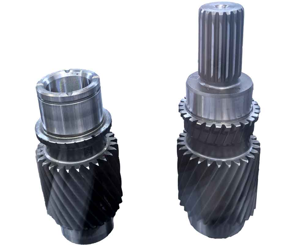
In recent years, the electric vehicle and robotics markets have experienced rapid growth. Gears, as critical mechanical components in these systems, have driven extensive research into advanced gear cutting techniques. Conventional methods like hobbing or shaping require specialized tools (hobs or shapers) that are constrained to predetermined modules and pressure angles, making them economically impractical for customized small-batch production. Form milling using profile cutters presents similar limitations due to gear-specific tool geometry. While 5-axis machining centers offer flexibility through CAM-generated toolpaths, their accessibility is limited for smaller workshops. To address these challenges, we propose a novel gear cutting method utilizing a conical end mill that enables the machining of gears with diverse specifications (module, pressure angle, tooth count) without tool changes. This approach operates on both 5-axis machining centers and universal milling machines equipped with a feed-synchronization mechanism, significantly enhancing flexibility for customized production.
1. Fundamental Principles of Gear Cutting with Conical End Mill
The core innovation involves using a conical end mill to generate gear teeth through coordinated motions. The tool reciprocates along the gear blank’s width while alternately feeding along the pitch circle tangent direction. For a single tooth space, the process involves:
- Tool reciprocation parallel to the gear axis (Z-direction)
- Synchronized tangential feed (Y-direction) and rotational indexing of the blank
The synchronization between tangential feed length (\(f_t\)) and blank rotation angle (\(\theta_w\)) is governed by:
$$ \theta_w = \frac{f_t}{r_0} = \frac{2f_t}{mz} $$
where \(r_0\) is the pitch radius, \(m\) is the module, and \(z\) is the number of teeth. This kinematic relationship ensures the generation of precise involute surfaces relative to the workpiece rotational axis. After completing one tooth space, the blank indexes by a pitch angle (\(\theta_i = \frac{2\pi}{z}\)), repeating the process for all teeth.

2. Parameter Adjustment Methodology
A key advantage of this gear cutting strategy is its adaptability to varied gear specifications through kinematic adjustments:
| Parameter | Adjustment Method | Governing Equation |
|---|---|---|
| Module (\(m\)) | Control groove depth (\(h\)) | \( h = 2.25m \) |
| Pressure Angle (\(\alpha\)) | Tilt toolpath plane by \(\Delta\alpha\) relative to blank axis | \( \Delta\alpha = \alpha – \alpha_t \) (\(\alpha_t\): tool half-cone angle) |
| Number of Teeth (\(z\)) | Modify indexing angle (\(\theta_i\)) | \( \theta_i = \frac{2\pi}{z} \) |
This parametric flexibility eliminates the need for dedicated tooling per gear specification, overcoming a fundamental limitation in conventional gear cutting processes.
3. Extended Capabilities: Helical and Curvilinear Gears
The methodology extends beyond spur gears to complex geometries:
3.1 Helical Gear Cutting
For helical gears, the tool maintains reciprocation along the Z-axis while the blank rotates synchronously with the helix angle (\(\beta\)). The axial displacement (\(l_a\)) and rotational displacement (\(\theta_a\)) follow:
$$ f_a = l_a \tan\beta $$
$$ \theta_a = \frac{f_a}{r_0} = \frac{2l_a \tan\beta}{mz} $$
This synchronization generates the required helical tooth flank geometry during the gear cutting operation.
3.2 Curvilinear Tooth Line Gear Cutting
Arbitrary tooth line profiles (e.g., circular arc) are achieved by programming the functional relationship between axial position (\(x\)) and rotational displacement:
$$ \theta_x = \frac{2f(x)}{mz} $$
where \(f(x)\) defines the desired curve shape. This capability enables the production of specialized gears like Wildhaber-Novikov designs with minimal setup changes.
4. Implementation on 5-Axis Machining Centers
The gear cutting method integrates directly with standard 5-axis CNC workflows. For vertical machining centers:
- Rotary axes (A/B) tilt the blank by 90°
- C-axis controls rotation and indexing
- Tool moves in zigzag pattern tangential to pitch cylinder
| Component | Material | Specifications |
|---|---|---|
| Workpiece | Engineering Plastic | Module: 2.5mm, Teeth: 34 Pressure Angle: 20°, Helix: 0° & 20° |
| Conical End Mill | High-Speed Steel | Tip Ø: 1.5mm, Length: 5mm Half-Cone Angle: 20°, Shank Ø: 6mm |
| Cutting Conditions | Spindle: 3,000 rpm, Feed: 300 mm/min, Feed/Rev: 0.1mm | |
Results demonstrated high precision in gear cutting, with common normal length deviations under 10μm for spur gears. Total machining time averaged 60 minutes per gear, validating the method’s accuracy and efficiency.
5. Implementation on Universal Milling Machines
For workshops without 5-axis capabilities, a mechanical feed-synchronization system enables gear cutting on conventional mills. The system features:
- Rack-and-pinion mechanism linking Y-axis feed to blank rotation
- Adjustable pivot point for tooth count variation (\(z\))
- Indexing mechanism governed by: \(\theta_i = \frac{2\pi}{z}\)
| Parameter | Value |
|---|---|
| Spindle Speed | 1,000 rpm |
| Feed Rate | 200 mm/min |
| Feed per Revolution | 0.2 mm |
| Workpiece Material | Engineering Plastic |
| Gear Specifications | Module: 2.5mm, Pressure Angle: 20°, Teeth: 31 |
Comparative analysis with hobbed gears showed maximum tooth profile deviation of 0.05mm. Variable module gears (1-2.5mm) were machined on a single blank by adjusting depth of cut, demonstrating exceptional flexibility in gear cutting operations.
6. Conclusion
This gear cutting methodology fundamentally transforms small-batch gear manufacturing by enabling:
- Single-tool production across diverse modules (1-2.5mm), pressure angles, and tooth counts
- High-precision implementation on 5-axis centers (≤10μm deviation)
- Practical adaptation for universal mills via synchronization system (0.05mm profile tolerance)
- Extended capability for helical and curvilinear tooth geometries
The approach significantly reduces barriers to customized gear production, particularly benefiting R&D, prototyping, and low-volume manufacturing where conventional gear cutting methods prove economically impractical. Future work will focus on optimizing cutting parameters for metallic alloys and enhancing surface finish quality.
