
Internal gearing power honing is a critical finishing process for hardened gears, generating unique “herringbone” surface textures that significantly reduce transmission noise. This study establishes comprehensive mathematical models for honing force prediction and dynamic characteristics analysis, addressing the periodic fluctuations in honing forces that induce self-excited vibrations during gear honing operations. These vibrations adversely affect surface quality, manufacturing accuracy, and tool life, potentially causing significant economic losses through premature wheel failure.
Fundamentals of Internal Gearing Power Honing
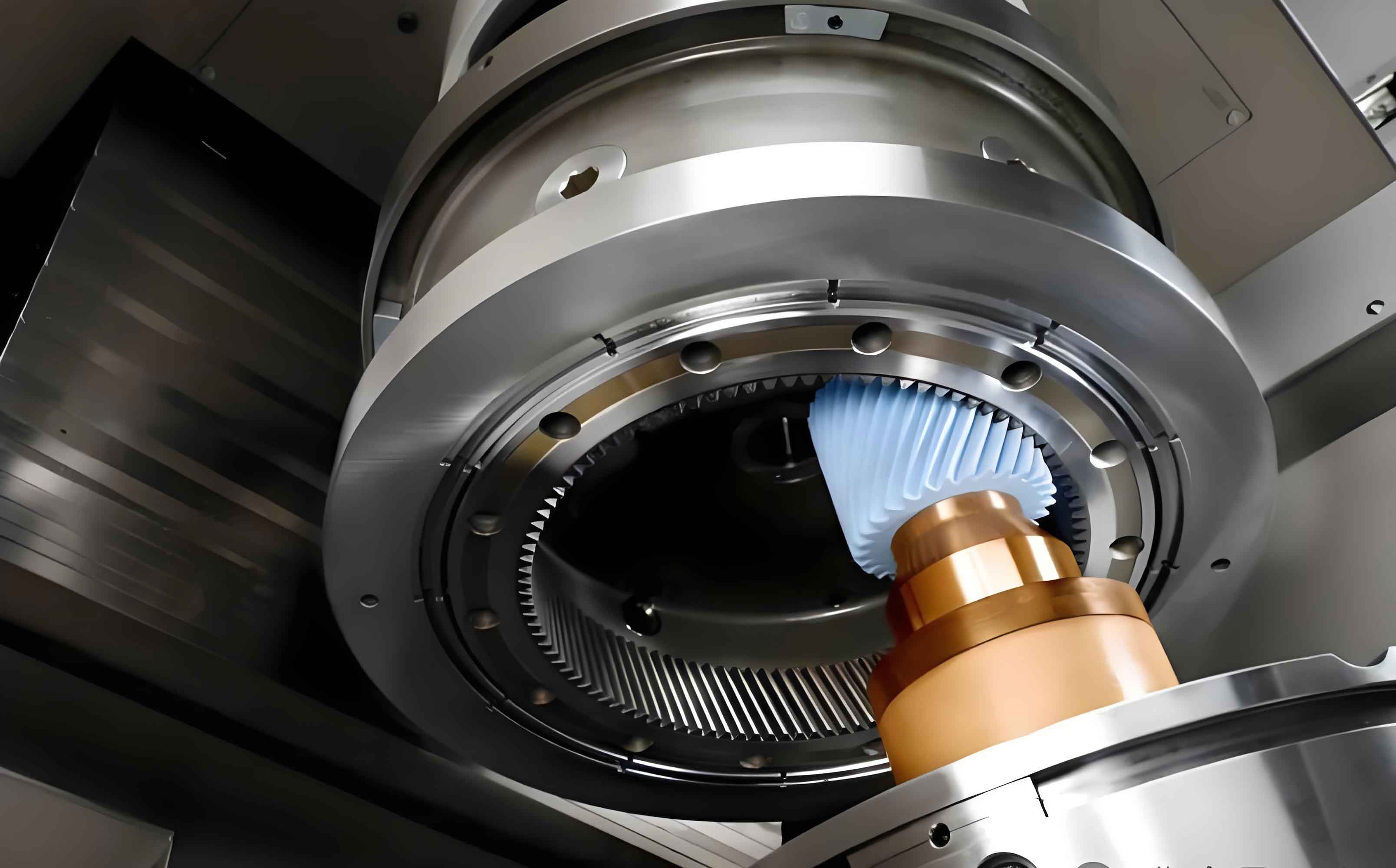
Internal gearing power honing operates through conjugate meshing between an internal honing wheel and external workpiece gear with crossed axes. The shaft angle Σ is determined by:
$$ \Sigma = \beta_1 – \beta_2 $$
where β₁ and β₂ represent the helix angles of the workpiece gear and honing wheel, respectively. The electronic gearbox maintains precise velocity synchronization:
$$ \frac{\omega_2}{\omega_1} = \frac{Z_1}{Z_2} \pm \frac{v_z}{360 \sin \Sigma} \cdot \frac{m_n}{Z_1} $$
Three distinct feed methodologies exist for gear honing:
| Process | Feed Direction | Precision | Efficiency | Application |
|---|---|---|---|---|
| Radial Feed Honing | X-axis only | Medium | Highest | Honing wheel width > gear width |
| Radial-Axial Intermittent | X and Z-axis sequentially | Highest | Lowest | High-precision small batches |
| Radial-Axial Continuous | X and Z-axis simultaneously | High | Medium | Large-scale production |
The contact line between workpiece and honing wheel during gear honing is derived through spatial meshing theory:
$$ \begin{cases} x_1 = r_{b1} [ \cos(\sigma_0 + \theta + \lambda) + \lambda \sin(\sigma_0 + \theta + \lambda) ] \\ y_1 = r_{b1} [ \sin(\sigma_0 + \theta + \lambda) – \lambda \cos(\sigma_0 + \theta + \lambda) ] \\ z_1 = p \theta \\ f(\lambda, \theta, \phi_1) = 0 \end{cases} $$
where rb₁ denotes base circle radius, σ₀ is the involute starting angle, θ is the spiral elevation angle, λ represents the involute expansion angle, and p is the spiral parameter.
Honing Force Modeling
The gear honing force comprises three components: chip formation force, friction force, and ploughing force. The unit-length honing force model integrates these components:
$$ F_n’ = K \frac{V_w}{V_c} a + K_1 \frac{V_w}{V_c} \sqrt{\frac{a}{d_e}} + K_2 \left( \frac{V_w}{V_c} \right)^{a_0} d_s^{b_0} a^{c_0} C_a^{1/2} d_e^{1/2} $$
$$ F_t’ = K’ \frac{V_w}{V_c} a + K_3 \frac{V_w}{V_c} \sqrt{\frac{a}{d_e}} d_e + K_4 \left( \frac{V_w}{V_c} \right)^{a_0} d_s^{b_0} a^{c_0} C_a^{1/2} d_e^{1/2} $$
Critical coefficients for the honing force model are:
| Parameter | Value | Parameter | Value |
|---|---|---|---|
| K | 41,217 | K’ | 23,081 |
| K₁ | 229,160 | K₂ | 1.287 |
| K₃ | 20,394 | K₄ | 3.24 |
| a₀ | 0.22 | b₀ | 0.33 |
| c₀ | 0.294 | – | – |
For multi-tooth engagement in gear honing, the contact ratio is calculated as:
$$ \varepsilon = \frac{\phi_t}{\tau} = \frac{\phi_{1max} – \phi_{1min}}{2\pi/Z_1} $$
Experimental validation on Fassler HMX-400 CNC gear honing equipment confirmed the model’s accuracy, showing:
$$ F_x \propto f_x $$
$$ F_x \propto \frac{1}{n_2} $$
where Fₓ is radial honing force, fₓ is radial feed per revolution, and n₂ is workpiece rotational speed.
Dynamic Characteristics of Honing Systems
Machine tool dynamics significantly influence gear honing precision. Material properties for dynamic analysis:
| Component | Material | Density (kg/m³) | Elastic Modulus (GPa) | Poisson’s Ratio |
|---|---|---|---|---|
| Bed | HT200 | 7,200 | 148 | 0.31 |
| Guideways | 45 Steel | 7,890 | 209 | 0.269 |
| Spindle | 28CrMnAlA | 7,800 | 210 | 0.278 |
| Honing Wheel | HT300 | 7,300 | 130 | 0.25 |
| Bearing | GCr15 | 7,830 | 219 | 0.30 |
Modal analysis revealed critical natural frequencies:
| System | Mode 1 (Hz) | Mode 2 (Hz) | Mode 3 (Hz) | Dominant Vibration |
|---|---|---|---|---|
| Complete Machine | 108.26 | 116.74 | 167.02 | Honing wheel vertical swing |
| Workpiece Spindle | 593.06 | 594.00 | 1135.4 | X/Y-direction oscillation |
| Honing Wheel System | 173.19 | 180.61 | 499.31 | Torsional vibration |
Harmonic response analysis identified resonance zones to avoid during gear honing operations. The excitation frequency range is:
$$ f = \frac{n_1 Z_1}{60} = \frac{n_2 Z_2}{60} $$
where n₁ and Z₁ are honing wheel speed (rpm) and teeth count, n₂ and Z₂ are workpiece gear speed and teeth count.
Dynamic Response in Honing Process
A 4-DOF dynamic model for gear honing vibration is established:
$$ \begin{cases} m_{x1} \ddot{x}_1 + c_{x1} \dot{x}_1 + k_{x1} x_1 = F_x(t) \\ m_{y1} \ddot{y}_1 + c_{y1} \dot{y}_1 + k_{y1} y_1 = F_y(t) \\ m_{x2} \ddot{x}_2 + c_{x2} \dot{x}_2 + k_{x2} x_2 = -F_x(t) \\ m_{y2} \ddot{y}_2 + c_{y2} \dot{y}_2 + k_{y2} y_2 = -F_y(t) \end{cases} $$
Dynamic displacement errors affect single pitch error:
$$ \varepsilon_x = [x_1(t) – x_1(0)] – [x_2(t) – x_2(0)] $$
$$ \Delta f_{pt} = 2 \left( \varepsilon_y + \frac{\varepsilon_x \tan \alpha_n}{\cos \beta} \right) $$
where αₙ is normal pressure angle and β is helix angle. Parameter studies revealed:
$$ \text{Peak-Peak } \varepsilon_x \propto \frac{1}{n_2} $$
$$ \Delta f_{pt} \propto f_x $$
demonstrating that higher workpiece speeds and lower feed rates reduce pitch errors in gear honing processes.
Conclusions and Perspectives
This research establishes comprehensive models for predicting honing forces and analyzing dynamic characteristics in internal gear honing processes. The honing force model accurately predicts force variations under different process parameters, validated through CNC gear honing experiments. Dynamic analysis reveals critical natural frequencies and vibration modes affecting honing precision, with harmonic response identifying resonance zones to avoid. The 4-DOF vibration model quantifies how dynamic displacement errors propagate into gear pitch errors, demonstrating that increased workpiece speeds (800-1800 rpm range studied) and reduced radial feeds (2-10 μm range) significantly decrease single pitch errors.
For enhanced gear honing precision, future research should investigate: 1) Honing force modeling with non-uniform stock distributions, 2) Combined thermo-mechanical effects on dynamic responses, 3) Advanced damping techniques for honing wheel systems, and 4) Real-time vibration suppression through adaptive control strategies. These advancements will further improve the stability and precision of gear honing processes for high-performance transmission applications.