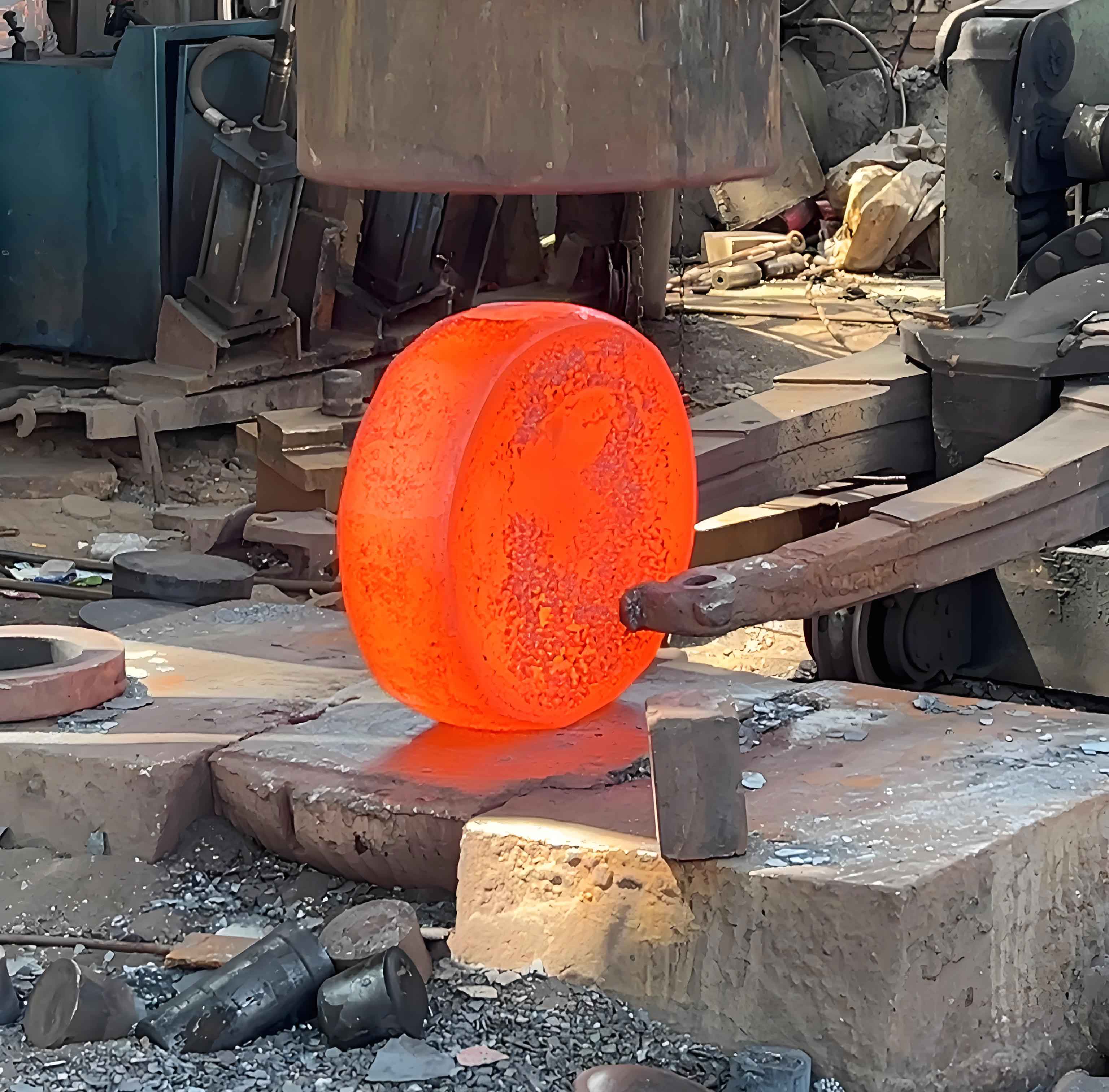
The evolution of gear forging technology represents a paradigm shift in manufacturing efficiency, material utilization, and mechanical performance. Unlike traditional machining methods that remove up to 40% of material, net-shape forging achieves near-final geometry with minimal waste. This research establishes a hybrid warm-forging/cold-sizing process capable of producing ISO grade 5-6 cylindrical gears without post-forging tooth machining. The methodology integrates finite element analysis (FEA) for die optimization and process simulation, addressing historical challenges in cylindrical gear forging where metal flow perpendicular to applied force complicates tooth formation.
Material Flow Dynamics in Warm Forging
Warm forging (850-950°C) balances formability and dimensional control. The flow stress $\sigma_f$ follows the temperature-dependent constitutive equation:
$$ \sigma_f = K \cdot \varepsilon^n \cdot \dot{\varepsilon}^m \cdot e^{\beta / T} $$
where $K$ is strength coefficient, $\varepsilon$ strain, $n$ work-hardening exponent, $\dot{\varepsilon}$ strain rate, $m$ strain-rate sensitivity, $\beta$ temperature coefficient, and $T$ absolute temperature. At 900°C, AISI 8620 steel exhibits optimal flow characteristics:
| Parameter | Value | Unit |
|---|---|---|
| K | 650 | MPa |
| n | 0.18 | – |
| m | 0.06 | – |
| $\beta$ | 3200 | K |
Die design leverages moving cavity architecture to enhance metal flow. As the upper die descends at 120 mm/s, frictional forces at the cavity-workpiece interface ($\mu$ = 0.3 with graphite lubricant) supplement deformation energy, reducing required load by 25-30% compared to fixed-cavity systems. Critical tooth corner filling occurs during the final 1.2% stroke where pressure peaks at 900 MPa.

Cold Sizing Mechanics and Springback Compensation
Cold sizing transforms warm-forged near-net shapes into precision gears through controlled radial compression. The elastic-plastic deformation follows:
$$ \varepsilon_{total} = \varepsilon_e + \varepsilon_p = \frac{\sigma}{E} + \left( \frac{\sigma}{K’} \right)^{1/n’} $$
where $\varepsilon_e$ is elastic strain, $\varepsilon_p$ plastic strain, $E$ Young’s modulus (210 GPa), and $K’$, $n’$ cold-working coefficients. Springback $\Delta r$ is modeled as:
$$ \Delta r = \frac{r_i \cdot \sigma_{res}}{E} \left( \frac{r_o^2 + r_i^2}{r_o^2 – r_i^2} + \nu \right) $$
with $r_i$, $r_o$ inner/outer radii, $\sigma_{res}$ residual stress, and $\nu$ Poisson’s ratio. Dual-pass cold forging optimizes residual stress distribution:
| Process | Residual Stress (MPa) | Surface Roughness Ra (μm) |
|---|---|---|
| Single-pass | -20 to -50 | 0.8-1.2 |
| Dual-pass | -80 to -110 | 0.5-0.8 |
FEA-driven die contouring accounts for position-dependent elastic deflection. When the gear midplane aligns with the die center, radial pressure induces controlled barrel distortion $D_b$:
$$ D_b = \frac{P \cdot r_m^3}{4EI} \left( 1 – \frac{z^2}{L^2} \right) $$
where $P$ radial pressure, $r_m$ mean radius, $E$ elastic modulus, $I$ moment of inertia, $z$ axial position, and $L$ die length. This intentional distortion compensates for non-uniform springback.
Process Integration and Validation
The hybrid gear forging sequence achieves dimensional accuracy through staged precision control:
| Stage | Tooth Profile Error (mm) | Surface Finish |
|---|---|---|
| Warm forging | ±0.05 | Ra 3.2 μm |
| Cold sizing | ±0.015 | Ra 0.8 μm |
Helical gear forging requires rotational accommodation in cold sizing dies. The torsional reaction torque $T_r$ is calculated as:
$$ T_r = \frac{\pi \mu P r_m^2 L \tan\alpha}{2} $$
where $\alpha$ helix angle. This necessitates angular clearance in press mounting and potential secondary reverse-pass forging for stress homogenization.
Industrial Implementation Challenges
Die manufacturing tolerances below 5 μm demand non-conventional processing. Wire EDM achieves contour accuracy for spur gears but requires post-machining polishing for $\sigma_{surface}$ < 50 MPa tensile stress. Helical die manufacturing follows the sequence: 1) Rough ECM (±0.1 mm), 2) Precision grinding (±0.02 mm), 3) Profile correction via CNC polishing.
Measurement methodology must address datumless validation. Coordinate measuring machines (CMM) use best-fit algorithms to minimize reference dependency. The optimization function minimizes:
$$ \min \sum_{i=1}^{n} \left[ (x_i – x_0)^2 + (y_i – y_0)^2 + (z_i – z_0)^2 – r_i^2 \right] $$
where $(x_0,y_0,z_0)$ is the provisional axis and $r_i$ the theoretical tooth profile.
Techno-Economic Analysis
Gear forging demonstrates compelling advantages for automotive production volumes (>100k units/year):
| Metric | Forging | Machining |
|---|---|---|
| Material utilization | 92-95% | 60-75% |
| Cycle time | 12-18 sec | 90-120 sec |
| Fatigue life improvement | 30-40% | Baseline |
The residual stress profile from cold forging follows a depth-dependent distribution:
$$ \sigma_{res}(z) = \sigma_{max} \left( 1 – \frac{z}{z_0} \right)^2 $$
where $\sigma_{max}$ is surface stress (-110 MPa) and $z_0$ attenuation depth (0.15 mm). This compressive layer increases bending fatigue resistance by impeding crack initiation.
Future Development Trajectory
Industrial implementation requires advancements in three domains: 1) In-process thermal monitoring using infrared pyrometry with $\Delta T$ < 10°C accuracy, 2) Adaptive die correction via real-time FEA feedback, 3) Standardization of datumless gear measurement protocols. Continued refinement promises extension to ISO 4 precision gears with cycle times under 10 seconds, solidifying gear forging as the manufacturing standard for high-volume powertrain applications.
