
Gear transmission systems in high-speed trains demand exceptional reliability, with surface contact fatigue being the predominant failure mode in enclosed gear systems. This study investigates surface cracking phenomena in S40C steel gears subjected to induction hardening. Surface-initiated grinding cracks represent a critical failure mechanism that compromises gear integrity through subsurface crack propagation under cyclic loading.
Experimental Methodology
Comprehensive failure analysis was conducted on cracked gears using multiple techniques:
Chemical Composition Analysis
Material composition was verified against S40C specifications (Table 1). All elements were within required limits, eliminating material non-conformance as a failure factor.
| Element | C | Si | Mn | P | S | Cr | Ni | Cu |
|---|---|---|---|---|---|---|---|---|
| Sample | 0.41 | 0.22 | 0.80 | 0.01 | 0.02 | 0.16 | 0.03 | 0.01 |
| Specification | 0.37-0.43 | 0.15-0.35 | 0.60-0.90 | ≤0.03 | ≤0.03 | ≤0.25 | ≤0.25 | ≤0.25 |
Macro/Microscopic Examination
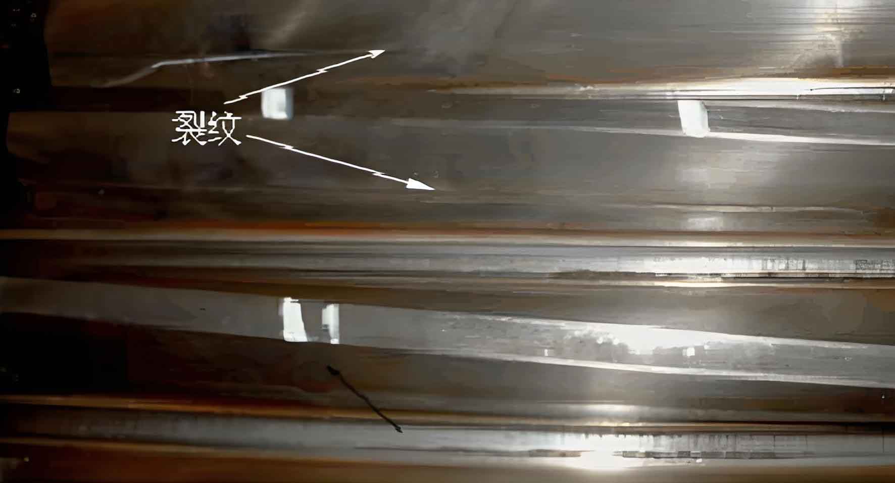
Magnetic particle inspection revealed grinding cracks near the pitch circle with distinct characteristics:
- Cracks formed closed-loop patterns at 15° angles to grinding direction
- T-junction analysis indicated primary crack initiation followed by bidirectional propagation
- Microscopy showed intact grinding marks adjacent to cracks with minimal wear evidence
Metallographic Analysis
Cross-sectional analysis through grinding cracks identified critical features:
| Location | Microstructure | Microhardness (HV1) | Depth from Surface |
|---|---|---|---|
| Cracked Surface | Tempered troostite | 420 | 0-50 μm |
| Sub-surface (Crack Origin) | Tempered martensite + troostite | 520 | ~400 μm |
| Normal Surface | Tempered martensite | 580 | 0-50 μm |
| Core Material | Pearlite + ferrite | 250 | >1.5 mm |
Key observations:
- Crack initiation at 0.4 mm depth corresponding to maximum Hertzian stress location
- 0.5 mm deep heat-affected zone with accelerated etching response
- Distinct microstructural degradation from surface to core
Microhardness Profiling
Hardness mapping revealed significant surface degradation:
- Surface hardness reduction of 160 HV1 (580→420) in damaged zones
- Hardness recovery to baseline values beyond 0.5 mm depth
The hardness gradient follows:
$$ H(d) = H_0 – \Delta H \cdot e^{-k \cdot d} $$
Where $H_0$ = base hardness (580 HV1), $\Delta H$ = hardness deficit (160 HV1), $k$ = thermal decay constant, $d$ = depth (mm)
Mechanism of Grinding Crack Formation
Grinding cracks originate from localized thermal damage during finishing operations. The mechanism involves:
Thermal Damage Progression
- Grinding friction elevates surface temperature to 300-400°C
- Martensite tempering transforms surface microstructure to troostite
- Phase transformation induces tensile residual stresses
- Microcrack nucleation at grain boundaries
The thermal stress during grinding is given by:
$$ \sigma_{thermal} = \alpha \cdot E \cdot \Delta T $$
Where $\alpha$ = thermal expansion coefficient, $E$ = Young’s modulus, $\Delta T$ = temperature gradient
Contact Fatigue Development
Subsurface crack propagation occurs through contact fatigue mechanisms:
$$ \tau_{max} = 0.3 \cdot \sigma_H $$
Where $\tau_{max}$ = maximum shear stress, $\sigma_H$ = Hertzian contact stress
Critical failure occurs when:
$$ \tau_{max} > S_{shear} $$
Where $S_{shear}$ = material shear strength
The altered hardness profile creates a critical weakness at 0.4 mm depth where:
- Maximum shear stress coincides with minimum material strength
- Cyclic stress concentration exceeds fatigue threshold
- Cracks propagate parallel to surface before upward deflection
Comparative Failure Modes
Grinding cracks initiate distinct failure mechanisms compared to other defects:
| Failure Mode | Crack Initiation Depth | Primary Cause | Hardness Profile |
|---|---|---|---|
| Grinding Cracks | 0.3-0.5 mm | Thermal softening | Surface hardness reduction |
| Insufficient Hardening | Variable | Inadequate quenching | Gradual hardness transition |
| Lubrication Failure | Surface | Frictional heating | Uniform reduction |
| Deep Spalling | Case-core interface | Shallow hardening depth | Abrupt hardness drop |
Stress-Structure Interaction
The relationship between shear stress distribution and material strength governs grinding crack propagation:
$$ \tau(z) = \tau_{max} \cdot \sqrt{1 + \left(\frac{z}{a}\right)^2} – \frac{z}{a} $$
Where $z$ = depth below surface, $a$ = contact half-width
Material strength follows the hardness gradient:
$$ S(z) = k \cdot H(z) $$
Where $k$ = material constant (~3 for steels)
Failure initiates when:
$$ \tau(z) \geq S(z) $$
Preventive Measures for Grinding Cracks
Mitigation strategies for grinding cracks include:
Process Controls
- Optimized grinding parameters: $Q_w’ = a_e \cdot v_w$ (Specific removal rate)
- Enhanced coolant delivery: Minimum flow 20 L/min·mm wheel width
- Dressing frequency: $N_d = C \cdot v_s / v_w$ (Dressing passes per workpiece)
Quality Verification
- Nital etching for burn detection
- Barkhausen noise analysis
- X-ray diffraction residual stress measurement
Conclusion
Grinding cracks in S40C gears originate from thermally-induced surface degradation during finishing operations. The mechanism involves:
- Grinding-induced tempering creating a 0.5 mm deep softened zone
- Hardness reduction from 580 HV1 to 420 HV1 at the surface
- Crack nucleation at 0.4 mm depth coinciding with maximum shear stress
- Progressive crack propagation under cyclic contact loading
These grinding cracks significantly reduce gear service life by creating initiation sites for contact fatigue failures. Prevention requires stringent control of grinding parameters and thermal management during finishing operations. Continuous monitoring of grinding temperatures and post-process quality verification are essential for preventing such subsurface defects in high-performance gear systems.