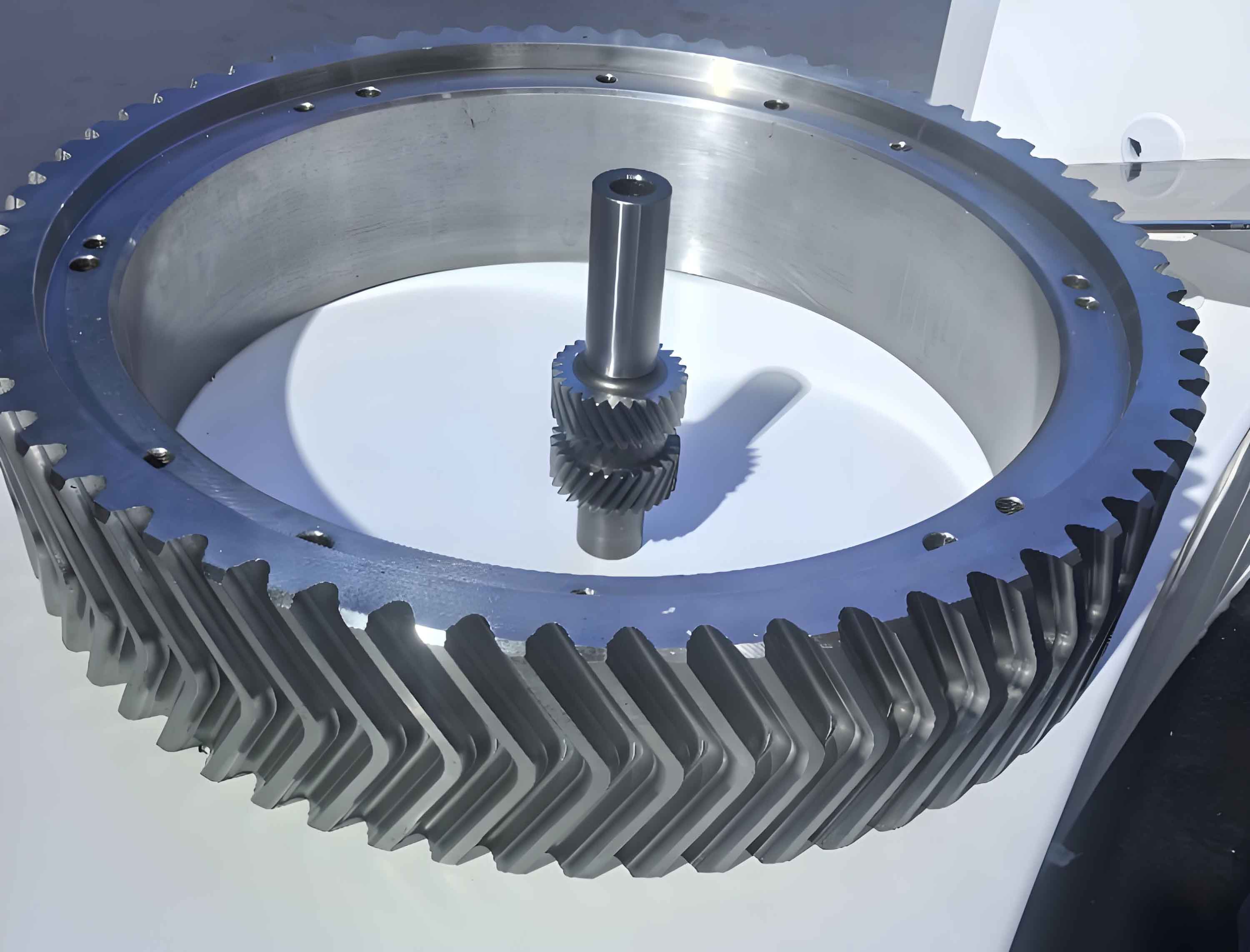
Aerospace spiral bevel gears are critical transmission components due to their smooth power transfer, high-speed compatibility, minimal noise, and low vibration. However, their high-load, high-speed operational demands necessitate exceptionally strict precision in gear machining. The core challenge lies in tooth surface manufacturing and inspection. Traditional processes involve face milling, heat treatment, and face grinding, followed by coordinate measuring machine (CMM) inspection, meshing tests, and dynamic contact pattern validation. Dynamic contact patterns directly influence operational stability, lifespan, and noise, making precise tooth surface control imperative. Digital closed-loop manufacturing integrates design, gear machining, and inspection into a cohesive system, enabling engineering standardization, high efficiency, superior quality, and cost-effectiveness. This approach ensures interchangeability and eliminates post-assembly adjustments, offering significant economic and societal benefits.

1. Digital Modeling Technology for Spiral Bevel Gears
Mathematical modeling simulates contact patterns before physical gear machining. Software compares simulated patterns against design specifications and actual roll-test results, iteratively optimizing parameters until compliance is achieved.
1.1 Modeling Process
Digital modeling uses fundamental gear dimensions and cutting methods to derive tooth surface mathematical models. Input parameters include:
| Category | Parameters |
|---|---|
| Basic Geometric Data | Shaft angle, tooth count, module, spiral angle, hand of spiral, pressure angle |
| Tooth Form Parameters | Profile shift coefficient, lengthwise crowning, heightwise crowning, pressure angle error, flank twist |
The tooth surface topography is defined by the position vector \(\mathbf{r}\) and normal vector \(\mathbf{n}\):
$$
\mathbf{r}(u, \theta) = \begin{bmatrix}
x(u, \theta) \\
y(u, \theta) \\
z(u, \theta)
\end{bmatrix}, \quad
\mathbf{n}(u, \theta) = \frac{\partial \mathbf{r}}{\partial u} \times \frac{\partial \mathbf{r}}{\partial \theta}
$$
where \(u\) and \(\theta\) are surface parameters.
1.2 Meshing Pattern Simulation
Static contact patterns are optimized by adjusting flank modifications until alignment with design specifications. Dynamic patterns under operational loads are then simulated. Key steps include:
- Input power/torque loads.
- Solve the load distribution equation:
$$
\mathbf{K} \mathbf{\delta} = \mathbf{F}
$$
where \(\mathbf{K}\) is the stiffness matrix, \(\mathbf{\delta}\) is displacement, and \(\mathbf{F}\) is load vector. - Evaluate transmission error (TE):
$$
TE = \Delta \phi_2 – \frac{N_1}{N_2} \Delta \phi_1
$$
where \(N_1\), \(N_2\) are tooth counts and \(\Delta \phi\) is angular displacement.
1.3 Gear Machining Process
Traditional five-cut methods require paired manufacturing, limiting interchangeability and increasing scrap rates. Digital closed-loop gear machining uses optimized parameters from simulations to create “electronic master gears.” This enables:
- Uniform grinding allowances post-heat treatment.
- Batch interchangeability.
- Reduced scrap and costs.
2. Inspection and Error Compensation Technology
Precision measurement and feedback form the core of closed-loop gear machining. Post-gear machining inspection compares physical gears against digital models via CMMs. Deviations are compensated by:
| Step | Action |
|---|---|
| 1 | Measure actual tooth flank deviations \(\Delta \mathbf{r}(u, \theta)\). |
| 2 | Solve inverse kinematics to adjust machine-tool settings: $$ \Delta \mathbf{S} = \mathbf{J}^{-1} \Delta \mathbf{r} $$ where \(\mathbf{J}\) is the Jacobian matrix linking settings \(\mathbf{S}\) to flank points. |
| 3 | Iteratively re-machine and measure until \(\Delta \mathbf{r} \leq \epsilon\). |
Final validation involves assembly, dynamometer testing, and dynamic contact pattern verification.
3. Implementation of Closed-Loop Manufacturing
The workflow integrates all stages into a cohesive system:
- Design: Generate digital twin with optimized flank topography.
- Gear Machining: Mill/grind using compensated parameters.
- Inspection: Measure flank deviations via CMM.
- Feedback: Compute error compensation (\(\Delta \mathbf{S}\)).
- Iterate: Repeat steps 2–4 until convergence.
This closed-loop gear machining system resolves traditional challenges like low interchangeability and high scrap rates. Dynamometer tests confirm optimal dynamic contact patterns under operational loads, validating the approach.
4. Conclusion
Digital closed-loop manufacturing for aerospace spiral bevel gears merges computational modeling, precision gear machining, and real-time metrology. By simulating contact patterns and stresses pre-production, then compensating for deviations via iterative feedback, the system achieves:
- High-precision tooth flanks.
- Batch interchangeability.
- Reduced scrap and costs.
- Extended gear life and reliability.
This methodology elevates aerospace gear machining to unprecedented levels of accuracy and efficiency, with broad applicability across high-performance transmission systems.
