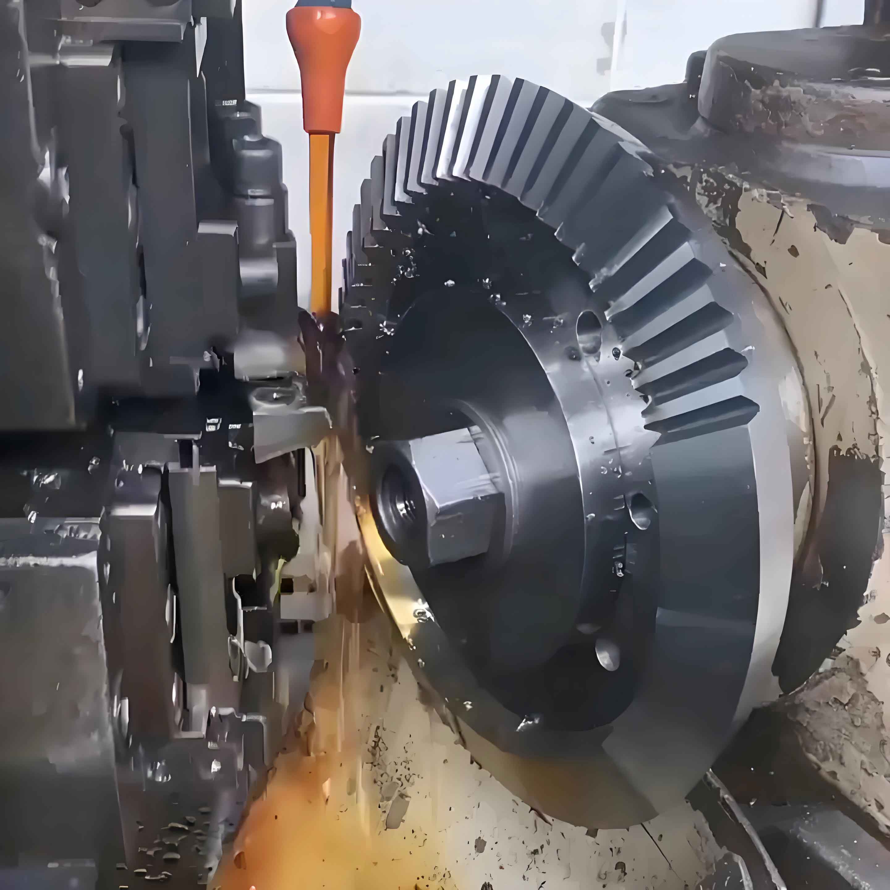
Gears are fundamental components for transmitting motion and torque in mechanical systems. The evolution of spiral bevel gear manufacturing has been revolutionized by CNC gear machining techniques, significantly enhancing production efficiency and quality. These complex gears, characterized by their curved teeth and conical geometry, enable precise power transmission between intersecting axes. Their high load capacity, smooth operation, and superior durability make them indispensable in demanding sectors like aerospace, automotive, and energy. Modern gear machining leverages parametric design and multi-axis CNC control to overcome traditional limitations in accuracy and efficiency.

Spiral bevel gear machining traditionally relied on the local conjugation principle, where the pinion tooth surface is derived from the gear tooth surface using reference points. This method calculates position vectors ($\vec{P}$), normal vectors ($\vec{N}$), and curvature parameters ($\kappa$) at discrete points:
$$\vec{P}_{pinion} = f(\vec{P}_{gear}, \vec{N}_{gear}, \kappa_{gear})$$
However, this approach suffered from inefficiency and limited precision. Modern CNC gear machining adopts Local Synthesis Methodology, which prescribes second-order contact conditions at reference points. This optimizes principal curvatures ($\kappa_1, \kappa_2$) and principal directions ($\vec{d}_1, \vec{d}_2$) on the pinion surface:
$$\begin{cases}
\kappa_{1}^{pinion} = g(\kappa_{1}^{gear}, \kappa_{2}^{gear}, \phi) \\
\kappa_{2}^{pinion} = h(\kappa_{1}^{gear}, \kappa_{2}^{gear}, \phi)
\end{cases}$$
where $\phi$ denotes the shaft angle. This mathematical foundation enables predictive control over tooth contact patterns.
Technological Evolution in Gear Machining
The development of spiral bevel gear machining progressed from mechanical generators to CNC systems. Initial methods like the Oerlikom process used continuous indexing to produce epicycloidal tooth profiles. CNC technology transformed gear machining by enabling:
- 5-axis simultaneous contouring for complex tooth geometry
- Parametric compensation for thermal and tooling deformations
- High-speed dry cutting (up to 300 m/min) with advanced tooling
Contemporary CNC gear machining centers integrate these capabilities, achieving micron-level accuracy through closed-loop feedback systems. The transition timeline highlights key innovations:
| Era | Technology | Precision Gain | Process Speed |
|---|---|---|---|
| 1950s | Mechanical Generators | ±50 μm | Low |
| 1980s | CNC Retrofit Systems | ±20 μm | Medium |
| 2000s | Integrated CNC Platforms | ±10 μm | High |
| Present | AI-Optimized Gear Machining | ±5 μm | Very High |
CNC Machining Principles
Spiral bevel gear machining requires synchronized multi-axis motion to generate complex tooth geometry. The fundamental kinematic chain in CNC gear machining involves:
$$\begin{bmatrix} X \\ Y \\ Z \\ A \\ C \end{bmatrix} = \mathbf{T} \cdot \begin{bmatrix} u \\ v \\ \theta \end{bmatrix}$$
where $\mathbf{T}$ is the transformation matrix correlating workpiece coordinates (u,v) and rotation ($\theta$) with machine axes (X,Y,Z,A,C). The cutting tool path follows the envelope surface defined by:
$$\frac{\partial \vec{S}}{\partial t} \cdot \vec{N} = 0$$
with $\vec{S}$ representing the cutter surface and $\vec{N}$ the surface normal. Modern implementations use parametric design equations:
$$x = (R + r \cos \beta) \cos \theta \\
y = (R + r \cos \beta) \sin \theta \\
z = r \sin \beta + P\theta$$
where $R$ = pitch radius, $r$ = cutter radius, $\beta$ = cutter rotation angle, $\theta$ = workpiece rotation, and $P$ = spiral parameter.
Process Optimization in Gear Machining
Effective CNC gear machining requires balancing cutting parameters to minimize tool wear while maximizing accuracy. Critical variables include:
| Parameter | Soft Gear Machining | Hard Gear Machining | Optimal Range |
|---|---|---|---|
| Cutting Speed (m/min) | 180-250 | 100-150 | 120-220 |
| Feed Rate (mm/tooth) | 0.15-0.25 | 0.08-0.15 | 0.10-0.20 |
| Depth of Cut (mm) | 0.8-1.2 | 0.3-0.6 | 0.5-1.0 |
| Tool Material | Coated Carbide | CBN/PCD | – |
The machining sequence employs strategic approaches:
- Gear Roughing: Multi-pass milling with HSS tools
- Semi-Finishing: Carbide cutters with coolant
- Finishing: Precision grinding with vitrified CBN wheels
Thermal deformation during gear machining follows the empirical relation:
$$\Delta D = \alpha \cdot \frac{F_c \cdot v_c}{k} \cdot t_m$$
where $\alpha$ = material coefficient, $F_c$ = cutting force, $v_c$ = cutting speed, $k$ = thermal conductivity, and $t_m$ = machining time. Compensation algorithms adjust tool paths using this model.
Implementation and Quality Control
Advanced CNC gear machining integrates multiple technologies for precision manufacturing:
- Virtual Simulation: Finite Element Analysis (FEA) predicts tooth deflection under cutting forces using:
$$\mathbf{K} \cdot \mathbf{u} = \mathbf{F}$$
where $\mathbf{K}$ = stiffness matrix, $\mathbf{u}$ = displacement vector, $\mathbf{F}$ = force vector
- Adaptive Control: Real-time monitoring adjusts parameters using:
$$v_c(t) = v_{c0} \cdot \left(1 – k_p \cdot \Delta T(t)\right)$$
with $v_{c0}$ = nominal speed, $k_p$ = compensation coefficient, $\Delta T$ = temperature deviation
- Metrology Integration: On-machine probing verifies tooth geometry against design parameters
Surface roughness ($R_a$) in gear machining correlates with process parameters:
$$R_a = C \cdot \frac{f^{1.2}}{r_\varepsilon^{0.4} \cdot v_c^{0.2}}$$
where $f$ = feed rate, $r_\varepsilon$ = tool nose radius, $v_c$ = cutting speed, and $C$ = material constant. Typical achieved values range from 0.8-1.6 μm for aerospace applications.
Future Advancements
CNC gear machining continues evolving through:
- Generative Design: AI-driven topology optimization for weight reduction
- Additive Hybrid: Combining laser deposition with precision machining
- Cyber-Physical Systems: Real-time data analytics for predictive maintenance
The computational framework for next-generation gear machining incorporates machine learning models:
$$\min_{\mathbf{p}} \left\{ w_1 \cdot t_m(\mathbf{p}) + w_2 \cdot C_t(\mathbf{p}) + w_3 \cdot \Delta(\mathbf{p}) \right\}$$
where $\mathbf{p}$ = process parameters, $t_m$ = machining time, $C_t$ = tool cost, $\Delta$ = deviation metric, and $w_i$ = weighting factors. This multi-objective optimization enhances gear machining efficiency by 25-40% while maintaining sub-5μm accuracy across production batches.
