
In gear manufacturing, gear hobbing stands as a pivotal process for generating high-precision gears across diverse industries like automotive, aerospace, and industrial machinery. This methodology enables the efficient production of spur, helical, and worm gears through a continuous generating motion. The core principle involves synchronized rotational and translational movements between the workpiece and a multi-toothed cutting tool called the hob. This article details a systematic approach to formulating gear hobbing processing plans and calculating production beats, essential for equipment selection validation and process optimization.
Fundamentals of Gear Hobbing and Kinematic Relationships
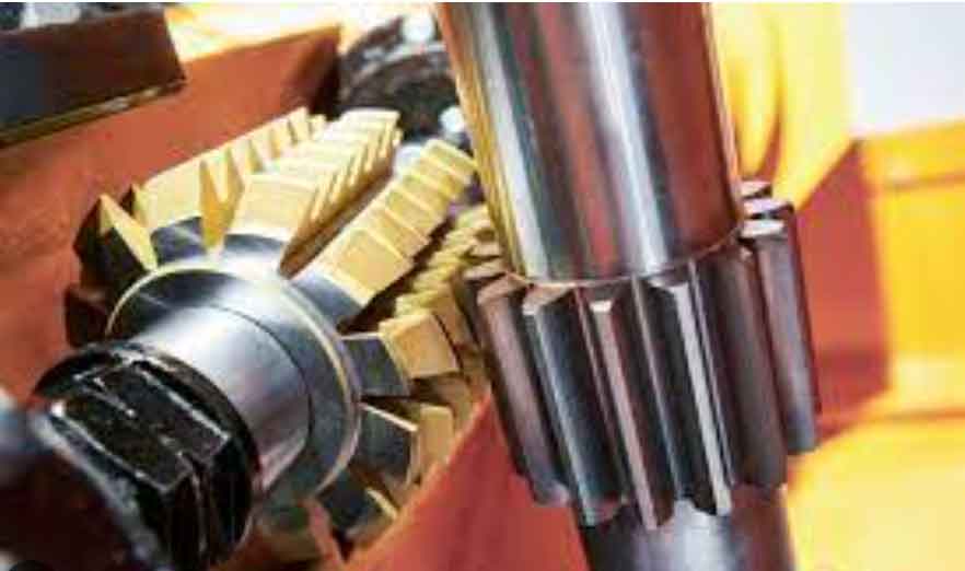
Gear hobbing operates on the generating cutting principle, simulating the meshing of a pair of crossed helical gears. The hob—a threaded cutting tool with gashes forming cutting edges—rotates continuously while the workpiece undergoes synchronized rotation. As the hob traverses axially along the gear blank, each hob tooth progressively removes thin layers of material from the gear slot. The involute tooth profile emerges as an envelope of successive instantaneous positions of the hob’s cutting edges. Tooth width is formed through axial feed motion, while tooth depth is achieved via radial infeed. Three primary gear hobbing methods exist:
- Axial Feed Method: Hob traverses parallel to the gear axis.
- Radial Feed Method: Hob feeds perpendicularly toward the gear center.
- Tangential Feed Method: Hob feeds along its own axis direction.
The kinematic chain governing gear hobbing establishes critical relationships. The rotational speed of the hob spindle ($n$) correlates with cutting speed ($v$) and hob diameter ($d₀$):
$$n = \frac{1000 \cdot v}{\pi \cdot d_0}$$
Simultaneously, the workpiece rotational speed ($n_{\text{workpiece}}$) must synchronize with the hob rotation and axial feed ($f$) to maintain correct generating motion:
$$n_{\text{workpiece}} = \frac{i \cdot n}{z_2} + \frac{f}{P_Z}$$
where $i$ is the number of hob starts, $z_2$ is the number of gear teeth, and $P_Z$ is the helical lead at the gear’s pitch diameter:
$$P_Z = \frac{\pi \cdot d_2}{\tan \beta_2}$$
$d_2$ represents the pitch diameter and $\beta_2$ denotes the helix angle.
Systematic Approach to Gear Hobbing Process Planning
Developing an effective gear hobbing plan requires meticulous analysis of gear specifications, machine capabilities, and tooling parameters to ensure feasibility and efficiency.
Step 1: Comprehensive Gear Drawing Analysis
Thoroughly examine the customer’s gear drawing to extract critical parameters:
- Gear Type & Parameters: Module ($m_n$), number of teeth ($z_2$), helix angle ($β_2$), pressure angle ($α_n$), pitch diameter ($d_2$), face width ($b$), addendum, dedendum.
- Accuracy Requirements: DIN/AGMA/JIS accuracy grade, permissible deviations (profile, lead, pitch).
- Material Properties: Blank hardness (HB), material grade (e.g., 45 Steel, 18CrMnTi, Grey Cast Iron).
- Process Constraints: Pre/post operations (pre-grinding, shaving), special requirements (surface finish, burr control).
Step 2: Gear Hobbing Machine Capability Assessment
Evaluate the gear hobbing machine’s technical specifications against gear requirements:
- Travel Limits: Radial distance (min/max center distance), axial travel, column clearance.
- Power & Dynamics: Spindle power (kW), maximum spindle torque ($M_{\text{t\_max}}$), spindle speed range ($n_{\text{min}}$ to $n_{\text{max}}$), table speed range.
- Rigidity & Accuracy: Machine stiffness, positioning accuracy, thermal stability.
Step 3: Workholding and Fixture Design
Determine optimal clamping strategy based on gear dimensions and geometry:
- Fixture Height & Diameter: Ensure adequate rigidity while minimizing overhang.
- Locating Surfaces: Define axial and radial datum surfaces for precise positioning.
- Interference Check: Verify clearance between fixture, gear blank, hob, and machine components during entry/exit.
Step 4: Gear Hobbing Tool Selection and Parameterization
Selecting and parameterizing the hob is critical for successful gear hobbing.
- Hob Material Selection: Dictated by required cutting speed ($v$).
Cutting Type Typical Speed Range (m/min) Recommended Hob Material Wet Hobbing < 120 High-Speed Steel (HSS), High-Performance HSS Dry Hobbing > 150 (Up to 250+) Powder Metallurgy HSS (PM-HSS), Carbide-Tipped, Coated Carbide - Hob Geometry Definition:
- Number of Starts ($i$): Governs productivity. Higher $i$ increases efficiency but requires higher table speeds. Ensure $i$ and $z_2$ are coprime to minimize pitch errors. Select $i$ based on machine table speed limits and $z_2$:
Gear Teeth ($z_2$) Recommended Hob Starts ($i$) < 30 1 (Single Start) > 30 2-4 (Multi-Start) - Hob Diameter ($d_0$): Determined by machine center distance limits and interference checks during entry/exit cuts. Larger diameters generally offer higher rigidity and accuracy but may limit speed.
- Hob Flute Count ($N$): Affects chip thickness and surface finish. More flutes allow finer feeds but reduce chip space.
- Number of Starts ($i$): Governs productivity. Higher $i$ increases efficiency but requires higher table speeds. Ensure $i$ and $z_2$ are coprime to minimize pitch errors. Select $i$ based on machine table speed limits and $z_2$:
- Cutting Parameter Optimization:
- Spindle Speed ($n$): Calculated based on target cutting speed ($v$) and hob diameter ($d_0$):
$$n = \frac{1000 \cdot v}{\pi \cdot d_0}$$ - Axial Feed Rate ($f$): Critical for surface finish, chip thickness ($h_{1max}$), and productivity. Two primary calculation methods exist:
- Chip Thickness Control: Set $h_{1max}$ typically between 0.20 mm and 0.25 mm for optimal tool life and surface integrity. Calculate $f$ using:
$$f = \frac{h_{1max} \cdot 1.9569 \cdot m_n \cdot (1.6145 \times 10^{-2} \cdot \beta_2 – 0.773) \cdot (0.4403 \cdot \beta_2 + 1.7162)}{(1.8102 \times 10^{-2} \cdot \beta_2 + 1.0607) \cdot (2.94 \times 10^{-2} \cdot \beta_2 – 0.6243) \cdot e^{(0.0446 \cdot \beta_2)}} \cdot \left(\frac{d_2}{N \cdot i}\right)^{0.5}$$
where $e$ ≈ 2.71828. For simplified planning, empirical values are often used:Module ($m_n$) Recommended $f$ (mm/rev) < 3 mm 1.5 – 2.0 > 3 mm 1.0 – 1.5 - Surface Waviness Control: Select $f$ based on permissible waviness depth ($δ$) for the subsequent process:
$$f = \frac{δ}{\cos \beta_2} \cdot \frac{4 \cos \beta_2}{\sin \alpha_n} \cdot \sqrt{\frac{d_2}{2}}$$Gear Hobbing Process Stage Permissible Waviness Depth ($δ$, µm) Precision Hobbing 0 – 3 Pre-Honing 5 – 10 Pre-Rolling 8 – 12 Pre-Shaving 10 – 20 Pre-Grinding 15 – 35
- Chip Thickness Control: Set $h_{1max}$ typically between 0.20 mm and 0.25 mm for optimal tool life and surface integrity. Calculate $f$ using:
- Spindle Speed ($n$): Calculated based on target cutting speed ($v$) and hob diameter ($d_0$):
Step 5: Axial Travel Calculation
Determine total hob axial travel ($L_{\text{total}}$) ensuring complete tooth engagement and clearance:
$$L_{\text{total}} = b + a + c$$
where $b$ is the gear face width, $a$ is the approach distance (typically 1-2 modules), and $c$ is the overtravel distance (typically 1-2 modules).
Step 6: Number of Passes and Depth of Cut Strategy
Optimize material removal strategy:
- Roughing: Usually one pass removing ~95% of total stock (≈ 2.25 * $m_n$).
- Finishing: Typically one or two light passes. First finish pass removes most remaining stock; final pass (0.2 mm – 0.5 mm) ensures surface quality and accuracy.
Step 7: Parameter Validation via Torque Calculation
Verify selected parameters against machine torque capacity using the empirical gear hobbing torque formula:
$$M_t = 18.2 \cdot m_n^{1.75} \cdot f^{0.65} \cdot T^{0.81} \cdot v^{-0.26} \cdot z_2^{0.27} \cdot K_1 \cdot K_2 \cdot K_3$$
where $T$ represents the relative depth of cut:
$$T = \frac{h}{2.25 \cdot m_n} \times 100\%$$
$h$ is the total cutting depth, and $K_1$, $K_2$, $K_3$ are correction factors:
| Material | Hardness (HB) | $K_1$ | $K_2$ | Helix Angle ($\beta_2$) | $K_3$ |
|---|---|---|---|---|---|
| 45 Steel | 220 | 1.00 | 1.00 (at 220 HB) | 0° | 1.00 |
| 40Cr | 221 | 1.08 | 1.05 (180 HB) | 10° | 1.07 |
| 18CrMnTi | 265 | 1.34 | 1.08 (200 HB) | 20° | 1.11 |
| 38CrMoAlA | 265 | 1.24 | 1.18 (240 HB) | ||
| Grey Cast Iron | 190 | 0.48 | 1.13 (260 HB) | ||
| 1.07 (280 HB) |
Ensure calculated torque ($M_t$) is less than the machine’s maximum spindle torque ($M_{\text{t\_max}}$) across the operating speed range.
Gear Hobbing Beat Time Calculation
The total production beat time ($T_{\text{beat}}$) for gear hobbing is the sum of machining time and non-cutting time:
$$T_{\text{beat}} = T_{\text{mach}} + T_{\text{non-cut}}$$
- Machining Time ($T_{\text{mach}}$): Time for actual cutting per gear.
$$T_{\text{mach}} = \frac{L_{\text{total}}}{f \cdot n_{\text{workpiece}}} = \frac{b + a + c}{f \cdot n_{\text{workpiece}}}$$
Substitute $n_{\text{workpiece}}$:
$$T_{\text{mach}} = \frac{b + a + c}{f} \cdot \frac{z_2}{i \cdot n}$$ - Non-Cutting Time ($T_{\text{non-cut}}$): Includes:
- Loading/Unloading ($T_{\text{load}}$): Manual or automated part handling.
- Tool Change Time ($T_{\text{change}}$): Distributed per part based on tool life ($T_{\text{life}}$) and machining time per part:
$$T_{\text{change\_per\_part}} = T_{\text{change}} \cdot \frac{T_{\text{mach}}}{T_{\text{life}}}$$ - Setup/Inspection ($T_{\text{setup}}$): Often amortized over batch size.
Thus, the comprehensive beat time is:
$$T_{\text{beat}} = \frac{b + a + c}{f} \cdot \frac{z_2}{i \cdot n} + T_{\text{load}} + \left(T_{\text{change}} \cdot \frac{T_{\text{mach}}}{T_{\text{life}}}\right)$$
Practical Application: Gear Hobbing Case Study
Evaluate the feasibility and efficiency of machining a spur gear on a YK3126 High-Speed Dry Gear Hobbing Machine.
Gear Specifications:
| Parameter | Value |
|---|---|
| Module ($m_n$) | 2 mm |
| Number of Teeth ($z_2$) | 17 |
| Pressure Angle ($\alpha_n$) | 20° |
| Helix Angle ($\beta_2$) | 0° |
| Face Width ($b$) | 7 mm |
| Pitch Diameter ($d_2$) | 34 mm |
| Material Hardness | < 240 HB (45 Steel) |
Hob Selection:
| Parameter | Value |
|---|---|
| Hob Diameter ($d_0$) | 65 mm |
| Number of Starts ($i$) | 1 (Single Start) |
| Material | S390 PM-HSS |
| Flute Count ($N$) | 12 |
Process Parameters & Validation:
| Parameter | Value | Calculation/Selection Basis |
|---|---|---|
| Cutting Speed ($v$) | 150 m/min | Hob Material Capability |
| Spindle Speed ($n$) | 734 rpm | $n = 1000 \cdot 150 / (\pi \cdot 65)$ |
| Axial Feed ($f$) | 1.5 mm/rev | Empirical Selection ($m_n$ < 3 mm) |
| Workpiece Speed ($n_{\text{workpiece}}$) | 43.1 rpm | $n_{\text{workpiece}} = (1 \cdot 734) / 17$ |
| Axial Travel ($L_{\text{total}}$) | 28 mm | $b$ = 7mm, $a$ = $c$ ≈ 10.5 mm (1.5 * $m_n$ * 3.5) |
| Required Torque ($M_t$) | ~120 N·m | Using Eq. (7) with $K_1=1.0$, $K_2≈1.18$, $K_3=1.0$ |
| Machine Max Torque | 381.6 N·m | YK3126 Spindle @ 734 rpm (Feasible: 120 < 381.6) |
Time Calculation:
| Time Component | Calculation | Value (min) |
|---|---|---|
| Machining Time ($T_{\text{mach}}$) | $(7 + 10.5) / (1.5 \cdot 43.1)$ | 0.43 |
| Loading Time ($T_{\text{load}}$) | Estimated | 0.25 |
| Tool Change Contribution* | Negligible (High Tool Life) | ~0.00 |
| Total Beat Time ($T_{\text{beat}}$) | ≈ 0.68 |
*Assuming long tool life reduces per-part change time contribution.
Conclusion
This structured methodology for gear hobbing process planning and beat time calculation provides a robust framework for validating machine capability, optimizing cutting parameters, and predicting production efficiency. By systematically analyzing gear requirements, machine limits, and tooling interactions, manufacturers can ensure feasible and economical gear hobbing operations. The integration of empirical formulas, material factors, and kinematic relationships enables accurate prediction of machining time, cutting forces, and overall beat times. This approach significantly enhances decision-making for gear production planning, equipment investment justification, and continuous process improvement in high-volume gear hobbing environments.