
Gear hobbing is widely adopted in manufacturing for producing high-quality spur and helical gears. Like many machining processes, it faces challenges in productivity and part quality. Physics-based simulations play a crucial role in addressing these challenges through precise process modeling, analysis, and optimization. Conventional operations like turning or milling benefit from analytical Cutter Workpiece Engagement (CWE) representations, simplifying digital simulations. However, the kinematic complexity of gear hobbing makes analytical CWE derivation impractical. While solid modeling techniques have been explored for gear hobbing simulation, computational demands escalate due to extensive 3D geometric updates. This study introduces a novel three-dimensional Dexel model approach to overcome these limitations, enhancing simulation efficiency and accuracy for gear hobbing operations.
Kinematic Model of Gear Hobbing
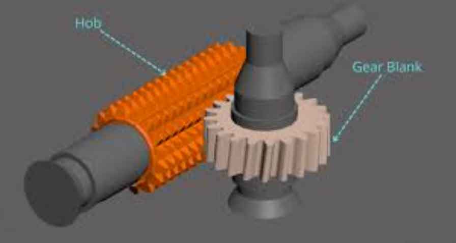
The kinematics of spur gear hobbing involve synchronized rotations of the hob (cutter) and gear (workpiece) at angular velocities \(\omega_c\) and \(\omega_g\), respectively. The hob advances along the gear width at axial feed velocity \(v_f\), with axial displacement \(d_a\). The hob axis is tilted by a rotation angle \(\gamma\) to ensure effective engagement. For identical hand orientations:
$$ \gamma = \beta – \eta $$
where \(\beta\) is the gear helix angle and \(\eta\) is the hob thread lead angle. The workpiece angular velocity \(\omega_g\) is determined by:
$$ \omega_g = \frac{N_g}{N_c} \left( 1 – \frac{\sigma v_f \sin \beta}{\pi N_g m_n} \right) \omega_c $$
Here, \(N_g\) is the number of gear teeth, \(N_c\) is the number of hob threads, \(m_n\) is the normal module, and \(\sigma = \text{sgn}(\beta) \cdot \text{sgn}(\eta) \cdot \text{sgn}(v_f)\) is a correction parameter. Cutting depth is typically set to \(d_c = 2.25m_n\). The initial center distance \(d_r\) is:
$$ d_r = r_{\text{tip}} + r_{ag} – d_c $$
where \(r_{\text{tip}}\) is the hob tip radius and \(r_{ag}\) is the gear addendum radius.
Three-Directional Dexel Model Framework
Our simulation engine uses ModuleWorks to convert triangular mesh models of the hob and gear blank into Dexel models. To reduce computational load, each hob tooth profile is modeled as an infinitesimally thin layer extruded from its rake face. The gear blank is represented as a cylinder. Kinematic equations govern relative motion, with interpolation applied at each timestep. The transformation between tool (\(r_c\)) and workpiece (\(r_w\)) coordinate systems is:
$$ \mathbf{r_w} = \mathbf{R}_{z,-\theta_g} \mathbf{T}_{y,d_r} \mathbf{T}_{z,-d_a} \mathbf{R}_{y,\gamma} \mathbf{T}_{x,-H} \mathbf{R}_{x,\theta_c} \mathbf{r_c} $$
where \(\mathbf{R}\) and \(\mathbf{T}\) denote rotation and translation matrices, \(\theta_g\) and \(\theta_c\) are angular positions, and \(H\) is axial displacement.
CWE Calculation and Undeformed Chip Extraction
CWE data extraction leverages the Dexel model’s parallel-plane intersection strategy. As illustrated below, the hob’s rake face intersects Dexel contours along XY, YZ, and ZX planes to generate 2D point clouds. Delaunay triangulation and Alpha shape reconstruction convert these into instantaneous undeformed chip geometries:
| Step | Process | Output |
|---|---|---|
| 1 | Intersect rake face with Dexel contours | 2D point cloud |
| 2 | Apply Delaunay triangulation | Triangular mesh |
| 3 | Alpha shape reconstruction | Undeformed chip geometry |
This assigns triangular areas to engagement nodes along the cutting edge, enabling efficient CWE updates during gear hobbing.
Cutting Force Prediction
Forces at each engagement node are calculated using an oblique cutting model. The tangential (\(F_t\)), feed (\(F_f\)), and radial (\(F_r\)) force distributions are:
$$ F_t = K_{tc} a + K_{te} b $$
$$ F_f = K_{fc} a + K_{fe} b $$
$$ F_r = K_{rc} a + K_{re} b $$
where \(K_{tc}\), \(K_{fc}\), \(K_{rc}\) are cutting force coefficients; \(K_{te}\), \(K_{fe}\), \(K_{re}\) are edge coefficients; \(a\) is chip area; and \(b\) is edge width. Cutting velocity at node \(P_i\) is:
$$ \mathbf{v_c} = \mathbf{\omega_c} \times \mathbf{r_{P_i,c}} – \mathbf{\omega_g} \times \mathbf{r_{P_i,g}} + \mathbf{v_f} $$
Scalar forces are vectorized using tangential, feed, and radial unit vectors for summation.
Experimental Setup and Validation
Tests used a Liebherr LC500 CNC hobbing machine. A Kistler 9123C rotating dynamometer measured cutting forces, with Kalman filtering compensating for structural dynamics. Workpiece material was 20CrNi2Mo steel, and hob material was ASP 2052 high-speed steel. Key parameters:
| Parameter | Value |
|---|---|
| Normal module (\(m_n\)) | 3.175 mm |
| Gear teeth (\(N_g\)) | 30 |
| Helix angle (\(\beta\)) | 20° |
| Hob threads (\(N_c\)) | 14 |
| Cutting speed | 55 m/min |
| Feed rate | 3.0 mm/rev |
Motion trajectories (B1, C2, X1, Z1 axes) aligned closely with simulations, validating kinematic accuracy. Cutting force predictions showed high fidelity:
| Direction | RMS Error | Std Dev Error |
|---|---|---|
| \(F_x\) | 58.2 N (11.2%) | 63.9 N (12.3%) |
| \(F_y\) | 60.4 N (11.6%) | 64.1 N (12.8%) |
| \(F_z\) | 108.7 N (4.6%) | 129.9 N (5.5%) |
Four additional tests under varying conditions confirmed robustness:
| Test | Conditions | Simulated \(F_{\text{axial}}\) (N) | Measured \(F_{\text{axial}}\) (N) | Simulated \(F_{\text{lateral}}\) (N) | Measured \(F_{\text{lateral}}\) (N) |
|---|---|---|---|---|---|
| 1 | 55 m/min, 7.143 mm, 3.0 mm/rev | 1,503 | 1,689 | 416 | 447 |
| 2 | 55 m/min, 7.143 mm, 1.8 mm/rev | 826 | 975 | 302 | 328 |
| 3 | 55 m/min, 7.143 mm, 1.2 mm/rev | 614 | 793 | 137 | 142 |
| 4 | 30 m/min, 6.734 mm, 3.0 mm/rev | 1,528 | 1,806 | 381 | 435 |
Conclusion
This study developed a three-dimensional Dexel model for cylindrical gear hobbing simulation, addressing computational inefficiencies in solid-modeling approaches. The framework accurately captures kinematics, CWE conditions, and undeformed chip geometry. Experimental validations on a Liebherr LC500 demonstrated RMS prediction errors of 4–12% across cutting force components. The method maintained accuracy under varying feed rates and cutting speeds, proving its robustness for gear hobbing optimization. Future work will refine geometric representations and integrate vibration prediction models.