
Back taper teeth structures are widely used in automotive transmissions. They generally fall into two categories: those with slanted roots and those with flat roots. Gear hobbing the former is relatively straightforward regarding cutter design and program debugging. However, achieving flat roots necessitates using an unequal pitch hobbing cutter, significantly complicating the gear hobbing program setup. This article delves into the principles and critical debugging considerations for gear hobbing flat-root back taper teeth using unequal pitch cutters, focusing on achieving rapid production changeover, minimizing scrap, and enhancing efficiency.
The fundamental challenge in gear hobbing flat-root back taper teeth lies in the geometry. Unlike slanted root versions where the root diameter forms a conical surface allowing radial feed variation, flat-root teeth maintain a constant cylindrical root diameter. This constant root diameter prevents simple radial feed adjustments to achieve the required taper. Consequently, the tooth thickness must decrease uniformly from the large end to the small end while maintaining a flat root plane. This demands precise synchronization between the hob’s axial (Z-axis) movement and its tangential (Y-axis) “shifting” motion relative to the gear blank.
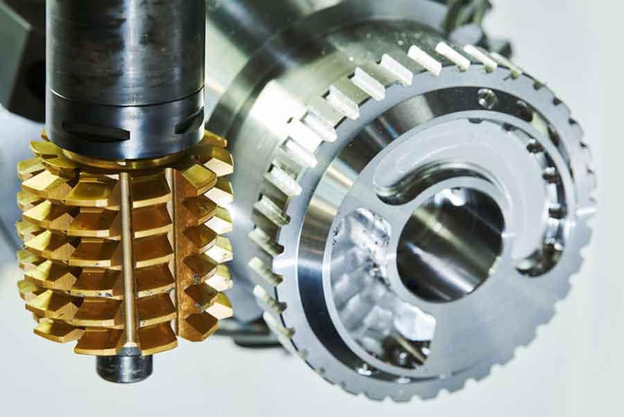
An unequal pitch hobbing cutter is essential for this gear hobbing process. Its tooth profile is deliberately designed with a continuously varying pitch. This variation allows the cutter to generate the necessary tooth thickness taper while maintaining the flat root condition when combined with coordinated Y and Z-axis movements on the CNC gear hobbing machine. The typical gear hobbing path involves a mid-line division strategy (Figure 5a referenced in source): the hob starts at a specific Y/Z position, feeds down the Z-axis while simultaneously shifting tangentially (Y-axis) to cut the upper taper section, reverses its Y-axis shift direction while continuing the Z-axis feed to cut the lower taper section, and finally retracts.
Geometric Principles and Gear Hobbing Kinematics
The geometry of back taper teeth is defined by key angles and differences (Figure 1 referenced in source):
- $B$: Face width
- $\alpha_h$: Root cone angle (for slanted root reference)
- $d_H$: Root radius depth difference (difference in root height between large and small ends)
- $\alpha_s$: Tooth flank cone angle
- $d_S$: Single flank thickness difference (tooth thickness difference between large and small ends)
The relationship governing the taper is expressed as:
$$d_H = B \tan \alpha_h$$
$$d_S = B \tan \alpha_s = d_H \tan \alpha_h$$
The critical link between the angles is:
$$\tan \alpha_s = \tan \alpha_h \tan \alpha_n$$
where $\alpha_n$ is the normal pressure angle. Achieving the specified $d_S$ requires ensuring the root height difference $d_H$, satisfying the root cone angle $\alpha_h$. For flat roots ($\alpha_h = 0$), $d_H = 0$, necessitating the coordinated gear hobbing motion with the unequal pitch cutter.
Program Parameter Relationships and Debugging Methodology
Debugging the gear hobbing program centers on establishing the correct initial hob positions (X, Y, Z) and understanding how adjustments to these positions affect the final gear dimensions, primarily the root diameter and the span measurement ($M_{op}$) across balls or pins at both large and small ends. A critical machine setup parameter is the Y-axis to Z-axis shift ratio ($K$), typically defined by the unequal pitch cutter design (e.g., $K = 0.3$ means Y-axis shift = 0.3 * Z-axis travel).
The primary measured outputs are:
- Root Diameter ($d_f$): Primarily controlled by the radial X-axis position.
- Span Measurement Large End ($M_{op,L}$)
- Span Measurement Small End ($M_{op,S}$)
Changes in the Z-axis and Y-axis starting positions directly impact $M_{op}$ at the large and small ends. Analysis of production gear hobbing data reveals the following sensitivity relationships:
| Axis Adjustment | Effect on Large End $M_{op,L}$ | Effect on Small End $M_{op,S}$ | Sensitivity Factor ($S$) |
|---|---|---|---|
| $\Delta Z$ (Overall Z-position increase) | $M_{op,L} – S_Z \Delta Z$ | $M_{op,S} + S_Z \Delta Z$ | $S_Z = \frac{|M_{op,L} – M_{op,S}|}{B}$ |
| $\Delta Y$ (Overall Y-position increase) | $M_{op,L} – S_Y \Delta Y$ | $M_{op,S} – S_Y \Delta Y$ | $S_Y = \frac{|M_{op,L} – M_{op,S}|}{(B / K)}$ |
Where $B$ is the face width and $K$ is the Y:Z shift ratio. For example, given a part where $M_{op,L} = 140.263$ mm, $M_{op,S} = 138.954$ mm, $B = 13.88$ mm, and $K = 0.3$:
- $S_Z = \frac{|140.263 – 138.954|}{13.88} \approx 0.094$ mm/mm
- $S_Y = \frac{|140.263 – 138.954|}{(13.88 / 0.3)} = \frac{1.309}{46.267} \approx 0.028$ mm/mm
This translates to the specific change rules:
$$\Delta Z_{+1mm} \rightarrow \Delta M_{op,L} \approx -0.094mm \text{ and } \Delta M_{op,S} \approx +0.094mm$$
$$\Delta Y_{+1mm} \rightarrow \Delta M_{op,L} \approx -0.028mm \text{ and } \Delta M_{op,S} \approx -0.028mm$$
Debugging Procedure for Gear Hobbing Flat-Root Back Taper Teeth
- Initial Setup: Input preliminary X, Y, Z coordinates into the gear hobbing program interface (Figure 7 referenced in source), ensuring the programmed Y-axis shift range ($Y_2 – Y_1$) satisfies $K = (Y_2 – Y_1) / (Z_2 – Z_1)$. Maintain the ratio $\Delta Z / \Delta Y = K$.
- Root Diameter Adjustment ($d_f$): Hob the first part. Measure the root diameter. Adjust the radial X-axis position based on the measured deviation from the target. Update the X-coordinate compensation value in the program. Hob another part and verify $d_f$ is within tolerance.
- Span Measurement ($M_{op}$) Difference Adjustment: With $d_f$ correct, measure $M_{op}$ at both large ($M_{op,L} = M_0 + \Delta M_L$) and small ($M_{op,S} = M_0 + \Delta M_S$) ends, where $M_0$ is the target span. The goal is first to equalize the deviation at both ends relative to the target difference, then shift both to target.
- Calculate the required overall Z-axis shift ($\Delta Z$) to equalize the deviations:
$$\Delta Z = \frac{(\Delta M_L – \Delta M_S)}{2 S_Z} \approx \frac{(\Delta M_L – \Delta M_S)}{2 \times 0.094}$$ - Apply $\Delta Z$ to all Z-axis coordinates: $Z_1′ = Z_1 + \Delta Z$; $Z_2′ = Z_2 + \Delta Z$; $Z_3′ = Z_3 + \Delta Z$. After this adjustment, $M_{op,L}$ and $M_{op,S}$ will both be approximately $M_0 + \frac{(\Delta M_L + \Delta M_S)}{2}$.
- Calculate the required overall Y-axis shift ($\Delta Y$) to bring both $M_{op,L}$ and $M_{op,S}$ to $M_0$:
$$\Delta Y = \frac{(\Delta M_L + \Delta M_S)}{2 S_Y} \approx \frac{(\Delta M_L + \Delta M_S)}{2 \times 0.028}$$ - Apply $\Delta Y$ to all Y-axis coordinates: $Y_1′ = Y_1 + \Delta Y$; $Y_2′ = Y_2 + \Delta Y$. This shifts both $M_{op,L}$ and $M_{op,S}$ down to $M_0$.
- Calculate the required overall Z-axis shift ($\Delta Z$) to equalize the deviations:
- Verification: Hob another part. Verify $d_f$, $M_{op,L}$, and $M_{op,S}$ meet specifications. Fine-tune using steps 2 and 3 if necessary.
Adjusting Tooth Flank Inclination (Slope Ratio)
Heat treatment distortion often requires adjusting the pre-heat treat tooth flank inclination ($f_{H\beta}$ or slope ratio $SR$). The slope ratio is defined as the change in tooth thickness per unit face width ($SR = d_S / B$). Since the unequal pitch hobbing cutter has a fixed built-in tooth thickness variation profile, the slope ratio is primarily controlled by the programmed magnitude of the Y-axis shift during gear hobbing.
To change the slope ratio from $SR_1$ to $SR_2$:
- Determine the current programmed Y-shift range: $\Delta Y_{current} = Y_2 – Y_1$.
- Calculate the required new Y-shift range proportional to the ratio of the desired slopes:
$$\Delta Y_{new} = \Delta Y_{current} \times \frac{SR_2}{SR_1}$$ - Adjust the Y-coordinates symmetrically to maintain the center position:
$$Y_1” = Y_1 – \frac{(\Delta Y_{new} – \Delta Y_{current})}{2}$$
$$Y_2” = Y_2 + \frac{(\Delta Y_{new} – \Delta Y_{current})}{2}$$
After adjusting the slope ratio via Y-shift magnitude, the span measurements $M_{op,L}$ and $M_{op,S}$ will likely need minor recalibration using the $\Delta Y$ adjustment described in Step 3 of the debugging procedure.
Conclusion
Successful gear hobbing of flat-root back taper teeth hinges on understanding the interaction between the unequal pitch hobbing cutter geometry and the synchronized Y/Z-axis motion of the CNC gear hobbing machine. The systematic debugging methodology presented, based on sensitivity factors $S_Z$ and $S_Y$ derived from the part geometry and cutter shift ratio $K$, enables rapid and precise program setup. By first correcting the root diameter via the X-axis, then methodically adjusting the Z and Y-axis positions to control the span measurement difference and absolute value, technicians can achieve production-ready programs efficiently. Furthermore, controlling the tooth flank inclination is readily achieved by scaling the programmed Y-axis shift magnitude. This approach has proven effective in industrial gear hobbing applications, ensuring stable production of high-quality flat-root back taper gears for demanding automotive transmissions while minimizing scrap and downtime during changeover.