
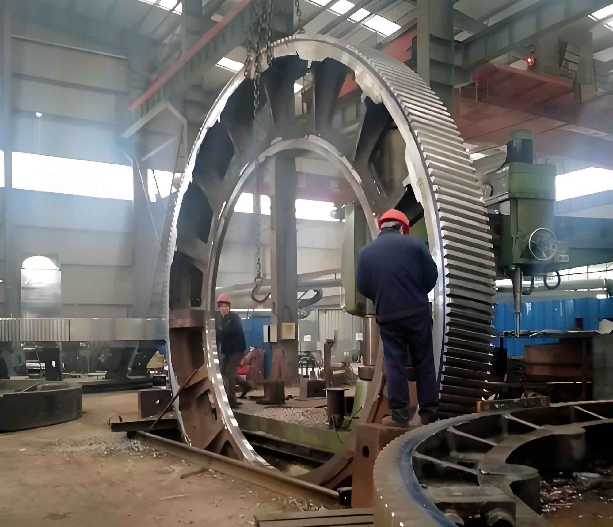
Spiral bevel gears serve as critical transmission components for transferring motion and power between intersecting or staggered shafts. Compared to straight or helical bevel gears, they exhibit superior characteristics including higher overlap coefficients, greater load capacity, smoother transmission, and reduced noise. These advantages make them indispensable in heavy-duty applications such as railway locomotives, marine vessels, mining equipment, and large-scale industrial machinery. The growing demand from China’s rapidly expanding heavy industry sector necessitates advanced manufacturing solutions for large gear components exceeding 700mm in diameter with grade 5 or higher precision.
Fundamental Gear Tooth Systems
Two primary tooth systems exist for large gear manufacturing:
| Tooth System | Tooth Trace | Tooth Height Profile | Post-Heat Treatment |
|---|---|---|---|
| Circular-Arc | Arc-shaped | Converging/Constant | Grinding |
| Extended Epicycloid | Epicycloid curve | Constant | Skiving |
The machining principle relies on simulating the meshing relationship between the imaginary generating gear (cradle) and the workpiece. The basic kinematic equation is expressed as:
$$\omega_w = \frac{N_c}{N_w} \omega_c$$
where \(\omega_w\) is workpiece angular velocity, \(\omega_c\) is cradle angular velocity, \(N_c\) is cradle tooth count, and \(N_w\) is workpiece tooth count.
Machine Tool Configuration and Parameters
Modern CNC gear cutting machines feature five-axis control systems with the following critical adjustment parameters:
| Parameter | Symbol | Function |
|---|---|---|
| Cradle Angle | \( \alpha_c \) | Controls tooth spiral orientation |
| Radial Distance | \( R_d \) | Determines tooth depth profile |
| Swivel Angle | \( \beta_s \) | Adjusts cutting head inclination |
| Eccentricity | \( e \) | Modifies cutter position |
| Machine Center to Back | \( X_b \) | Sets axial workpiece position |
The relationship between tool radius \( R_t \) and gear module \( m_n \) for large gear production follows:
$$ R_t = k \cdot m_n \cdot Z^{0.5} $$
where \( k \) is cutter coefficient (1.8-2.2), \( m_n \) is normal module, and \( Z \) is tooth count.
Precision Machining Methodology
For large gear components, constant tooth height systems offer computational simplicity through three fundamental conditions:
1. Pressure angle consistency: \( \alpha_1 = \alpha_2 = \alpha_n \)
2. Spiral angle stability: \( \beta_m = \beta_{ref} \pm \Delta\beta \)
3. Cutter radius optimization: \( R_c = f(m_n, Z, \beta_m) \)
The tooth surface generation process employs synchronized motions governed by:
$$ \begin{bmatrix} X \\ Y \\ Z \end{bmatrix} = R_z(\theta) \cdot T_x(S) \cdot \begin{bmatrix} r_c \cos\phi \\ r_c \sin\phi \\ p_c \phi \end{bmatrix} $$
where \( R_z \) is rotation matrix, \( T_x \) is translation matrix, \( r_c \) is cutter radius, \( \phi \) is rotation angle, and \( p_c \) is spiral parameter.
Technical Advancements
Key innovations in large gear manufacturing include:
1. Tooth Profile Optimization: Transition from conventional Oerlikon system to Klingelnberg-style constant height teeth simplifies adjustment and enables post-heat treatment grinding.
2. Multi-axis CNC Integration: Five-axis simultaneous control achieves complex kinematic relationships:
$$ \text{Position} = \sum_{i=1}^{5} C_i \cdot q_i(t) $$
where \( C_i \) are machine constants and \( q_i(t) \) are axis position functions.
3. Cutter Head Design: Modular tooling systems accommodate diameters up to 1800mm with automatic balancing mechanisms.
Processing Workflow
| Stage | Process | Tolerance (μm) |
|---|---|---|
| 1. Roughing | Face milling | ±150 |
| 2. Semi-finishing | Formate cutting | ±50 |
| 3. Heat Treatment | Carburizing & quenching | N/A |
| 4. Finishing | Grinding/skiving | ±10 |
| 5. Inspection | CMM & gear analyzer | ±5 |
Quality Control Metrics
For grade 5 precision large gear components, critical tolerances include:
$$ \text{Tooth alignment error} \leq 0.015 \cdot m_n + 5 \mu m $$
$$ \text{Profile deviation} \leq 0.07 \cdot m_n + 3.5 \mu m $$
$$ \text{Pitch error} \leq 0.09 \cdot m_n + 4.5 \mu m $$
where \( m_n \) is normal module in millimeters.
Conclusion
The adoption of constant tooth height systems combined with advanced CNC technology enables economical production of high-precision large gear components. This approach overcomes limitations of traditional duplex cutting methods while achieving surface roughness below Ra 0.8μm and tooth-to-tooth pitch errors under 12μm. Continued refinement of multi-axis machining strategies and in-process metrology will further enhance the manufacturing precision for heavy industrial applications requiring reliable power transmission solutions.