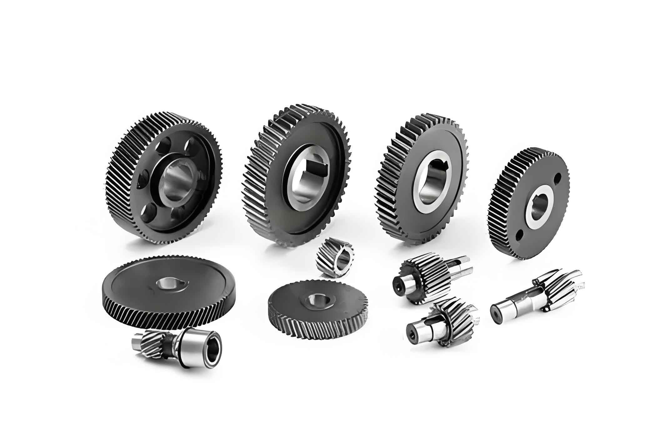
Helical gears are widely adopted in electric vehicle transmissions due to their high load capacity, smooth engagement, and manufacturing efficiency. This study investigates vibration characteristics under extreme operating conditions (up to 12,000 rpm) using a coupled bending-torsion-axial dynamic model. The analysis focuses on how time-varying mesh stiffness and meshing impacts influence system dynamics, providing critical insights for noise reduction in electric vehicle gear systems.

Dynamic Modeling of Electric Vehicle Gear Systems
A six-degree-of-freedom model was established for a high-speed helical gear pair from an electric vehicle reducer. Key parameters are listed in Table 1:
| Parameter | Pinion | Gear |
|---|---|---|
| Teeth (z) | 22 | 59 |
| Normal module (mm) | 2 | |
| Helix angle (°) | 32 | |
| Torque (N·m) | 100 | 268.2 |
| Bearing stiffness (N/m) | 8.08×10⁸ (radial) 6.85×10⁸ (axial) |
3.98×10⁸ (radial) 3.16×10⁸ (axial) |
The governing equations are expressed as:
$$
\begin{cases}
m_p \ddot{y}_p + c_{py} \dot{y}_p + k_{py} y_p = -F_y \\
m_p \ddot{z}_p + c_{pz} \dot{z}_p + k_{pz} z_p = -F_z \\
I_p \ddot{\theta}_p = -F_y R_p + T_p – F_s(t) R_p \\
m_g \ddot{y}_g + c_{gy} \dot{y}_g + k_{gy} y_g = F_y \\
m_g \ddot{z}_g + c_{gz} \dot{z}_g + k_{gz} z_g = F_z \\
I_g \ddot{\theta}_g = F_y R_g – T_g + F_s(t) R_g
\end{cases}
$$
where $F_y$ and $F_z$ represent dynamic mesh forces:
$$
F_y = \cos\beta \left\{ c_m \left[ \cos\beta (\dot{y}_p – \dot{y}_g + R_p \dot{\theta}_p – R_g \dot{\theta}_g) + \sin\beta (\dot{z}_p – \dot{z}_g) \right] + k(t) \left[ \cos\beta (y_p – y_g + R_p \theta_p – R_g \theta_g) + \sin\beta (z_p – z_g) \right] \right\}
$$
Time-Varying Mesh Stiffness Calculation
An improved Loaded Tooth Contact Analysis (LTCA) method calculated stiffness variations for the electric vehicle gear pair. Mesh stiffness combines geometric transmission error, bending deformation, and contact deformation:
$$
k(t) = \frac{P}{Z} = \frac{P}{c_1 + c_2 P + c_3 \sqrt[3]{P^2}}
$$
where $c_1$, $c_2$, and $c_3$ are coefficients determined through curve fitting. Under 100 N·m torque, stiffness fluctuates between 1.6×10⁸ and 2.8×10⁸ N/m with a 15.2% variation amplitude.
Meshing Impact Dynamics
Geometric interference during engagement generates impulse forces. Impact duration and magnitude are derived from kinematic relations:
$$
\Delta t = \frac{\Delta \phi_p}{\omega_1}, \quad F_s = v_s \sqrt{ \frac{I_p I_g}{(I_p (r’_g)^2 + I_g r_p^2)(q_s + q_r \cos^2 \theta)} }
$$
Impact duration increases with torque but exhibits diminishing growth (3%-8.4% of mesh cycle). Higher rotational speeds linearly amplify impact forces, correlating with increased dynamic load coefficients.
Vibration Response Analysis
Relative vibration acceleration along the line of action serves as the primary metric:
$$
a = \cos\beta (\ddot{y}_p – \ddot{y}_g + \ddot{q}) + \sin\beta (\ddot{z}_p – \ddot{z}_g)
$$
Three excitation conditions were analyzed:
1. Time-varying stiffness only: Resonance peaks occur at $n_0/3$, $n_0/2$, and $n_0$ (natural frequency). Post-resonance acceleration remains stable despite speed increases due to parametric excitation characteristics.
2. Meshing impacts only: Acceleration RMS grows linearly with rotational speed. Impact zones show negative acceleration spikes (12%-18% amplitude drop) due to follower wheel velocity mutation. Resonance appears at $n_0/4$, $n_0/3$, $n_0/2$, and $n_0$.
3. Combined excitation: Vibration amplification follows impact-dominant trends but with 22%-27% lower growth rates than pure impact excitation. High-frequency components (up to 20× mesh frequency) persist due to impulse characteristics.
| Excitation Condition | Acceleration RMS (m/s²) | Dominant Frequency |
|---|---|---|
| Stiffness only | 8.7 | 1× mesh frequency |
| Impacts only | 23.5 | 1× and 3× mesh frequency |
| Combined | 19.2 | Broadband (1-20× mesh freq) |
Design Implications for Electric Vehicle Gears
1. Above resonance speeds (>8,900 rpm), meshing impacts dominate vibration response in electric vehicle gear systems
2. Impact-induced acceleration increases 140%-160% from 4,000 to 12,000 rpm
3. Tooth modifications should prioritize impact reduction over stiffness optimization for high-speed electric vehicle gears
4. Spectral analysis reveals persistent high-frequency energy (15-20× mesh freq) under impact excitation
These findings provide critical guidance for optimizing high-speed electric vehicle gear designs, particularly regarding torque-density tradeoffs and NVH suppression strategies. Future work will explore micro-geometry optimizations targeting impact force mitigation.
