
Energy and environmental challenges are increasingly severe, with new energy vehicles gaining significant attention. Electric vehicles (EVs), recognized for their zero emissions, low noise, and diverse power sources, have become a focal point of global research. While EVs share structural similarities with internal combustion engine vehicles in body design, their powertrain systems and operating environments exhibit distinct differences. The EV transmission system eliminates torsional damping components like torque converters and clutches, resulting in an underdamped system. Additionally, it employs multi-stage reduction and limited-ratio gearing, shortening power transfer paths and substantially increasing load cycles. These characteristics introduce new theoretical and technical challenges, particularly in predicting transmission lifespan and system reliability—key bottlenecks in performance enhancement. This study focuses on a fixed-ratio high-speed helical electric vehicle gear, establishing a control model for the permanent magnet synchronous motor (PMSM) used in vehicles. Simulations based on the Urban Dynamometer Driving Schedule (UDDS) cycle yield dynamic motor output torque. This torque drives the electric vehicle gear, enabling derivation of contact stress spectra under cyclic conditions. The rainflow counting method processes these spectra to quantify stress amplitude-frequency relationships for high-speed helical gears.
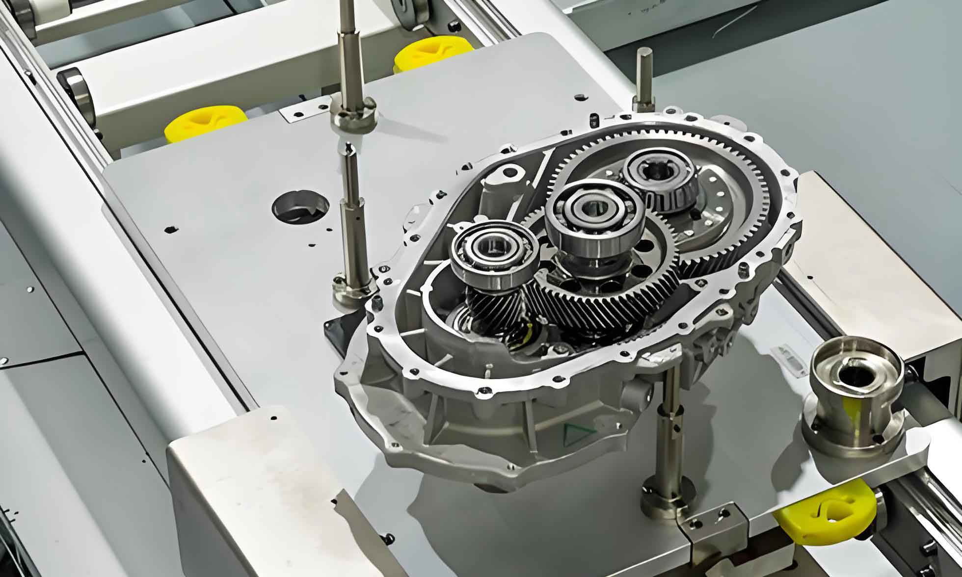
Electric motors deliver high starting torque, enabling low-speed constant-torque and high-speed constant-power operation with seamless speed control. To enhance efficiency, models like BAIC EV series and BMW i3 utilize fixed-ratio transmissions due to their simplicity and low manufacturing cost. The basic structure is shown below:
During motion, a vehicle’s driving force must balance resistance. Analyzing transmission loads requires examining both. The driving force \(F_t\) at the wheels relates to transmission input torque \(T_{tq}\) by:
$$F_t = \frac{T_{tq} \cdot i_0 \cdot \eta}{r}$$
where \(i_0\) is the final drive ratio, \(\eta\) is drivetrain efficiency, and \(r\) is wheel radius.
Resistances include rolling resistance \(F_f\), aerodynamic drag \(F_w\), gradient resistance \(F_i\), and acceleration resistance \(F_j\):
$$\sum F_k = F_f + F_w + F_i + F_j \quad (k=f,w,i,j)$$
The vehicle motion equation is thus:
$$F_t = \sum F_k$$
Motor load torque \(T_L\) follows:
$$T_L = \frac{r}{i_0 \cdot \eta} \cdot \sum F_k$$
| Symbol | Parameter | Unit |
|---|---|---|
| \(F_f\) | Rolling Resistance | N |
| \(F_w\) | Aerodynamic Drag | N |
| \(F_i\) | Gradient Resistance | N |
| \(F_j\) | Acceleration Resistance | N |
| \(i_0\) | Final Drive Ratio | – |
The PMSM model in the d-q reference frame provides the foundation for vector control. With \(i_d=0\) strategy, steady-state voltage equations are:
$$u_d = – \omega_e L_q i_q$$
$$u_q = \omega_e L_d i_d + \omega_e \psi_f$$
where \(u_d\), \(u_q\) are d/q-axis voltages, \(i_d\), \(i_q\) are currents, \(L_d\), \(L_q\) are inductances, \(\psi_f\) is flux linkage, and \(\omega_e\) is electrical speed. Torque production simplifies to:
$$T_e = \frac{3}{2} p \psi_f i_q$$
with \(p\) denoting pole pairs. This orthogonal alignment decouples torque and flux control. The implemented vector control framework regulates speed through q-axis current modulation.
Simulations in MATLAB/Simulink incorporate the PMSM model under UDDS cycling. Key motor parameters include:
| Parameter | Value | Unit |
|---|---|---|
| Rated Power | 90 | kW |
| Peak Torque | 280 | Nm |
| Flux Linkage \(\psi_f\) | 0.12 | Wb |
| Pole Pairs \(p\) | 4 | – |
Dynamic torque output exhibits high-frequency fluctuations and sharp transient peaks, critical for electric vehicle gear loading. This torque drives the helical electric vehicle gear pair. Maximum contact stress \(\sigma_H\) on the pinion is calculated using an equivalent spur gear approach:
$$\sigma_H = Z_E Z_H Z_\varepsilon Z_\beta \sqrt{\frac{K \cdot T_1}{b \cdot d_1^2} \cdot \frac{u + 1}{u}}$$
where \(Z_E\) is elasticity coefficient, \(Z_H\) is zone factor, \(Z_\varepsilon = 1\) is overlap factor, \(Z_\beta = \sqrt{\cos\beta}\) is helix angle factor, \(K\) is load factor, \(T_1\) is pinion torque, \(b\) is face width, \(d_1\) is pinion pitch diameter, and \(u\) is gear ratio. Stress-time histories under UDDS reveal complex, non-stationary patterns essential for electric vehicle gear durability assessment.
Rainflow counting extracts stress cycles (amplitudes \(\sigma_a\), means \(\sigma_m\)) from the spectrum. Statistical analysis confirms \(\sigma_m\) follows a normal distribution:
$$\sigma_m \sim \mathcal{N}(508, 82.3^2) \text{ MPa}$$
while \(\sigma_a\) adheres to a Weibull distribution. Cycle distribution characteristics are summarized below:
| Statistic | Stress Amplitude | Stress Mean |
|---|---|---|
| Distribution | Weibull | Normal |
| Mean Value | 184 MPa | 508 MPa |
| Standard Deviation | 67 MPa | 82.3 MPa |
| Dominant Cycle Range | 50-250 MPa | 400-600 MPa |
This research establishes a methodology for deriving physics-based dynamic load spectra for electric vehicle gears. By integrating motor control dynamics, transmission mechanics, and statistical cycle analysis, it overcomes the limitations of empirical load assumptions. The obtained distributions provide foundational data for fatigue life prediction and reliability modeling of EV transmission systems, particularly for high-speed helical gears operating under high-cycle fatigue regimes. Accurate load spectra enable optimized design and durability validation of electric vehicle gear systems, contributing to enhanced powertrain performance and longevity.