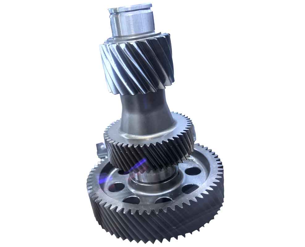
Traditional CAD methods face significant challenges when modeling complex 3D geometries like reverse gears, particularly bevel gears with precise involute profiles. This article presents an innovative reverse CAD methodology that transforms conventional design workflows. Unlike forward design requiring extensive programming, this approach leverages CAD software’s macro recording capabilities to automate parametric modeling. The core innovation lies in recording interactive modeling sequences as executable macros, then replacing critical dimensional constants with variables. This enables rapid regeneration of complex geometries like reverse gears through simple parameter modifications.
The reverse CAD workflow consists of four interconnected phases: interactive modeling, macro recording, parametric conversion, and automated regeneration. Initially, designers create a base model of the reverse gear interactively within the CAD environment. Simultaneously, the CAD system records all operations into a macro file. Key dimensional constants within this macro are identified and replaced with variables linked to gear parameters. Finally, executing this modified macro with new input values automatically generates updated reverse gear geometries. The mathematical foundation for involute tooth profiles is established through coordinate transformations:
$$x_c = r_c \sin \theta_c$$
$$y_c = r_c \cos \theta_c$$
$$\theta_c = \tan \alpha – \tan \alpha_c + \alpha_c – \alpha + \frac{0.5s}{r}$$
$$\alpha_c = \arccos\left(\frac{r_b}{r_c}\right)$$
where \(r_c\) represents the radial distance to point C on the tooth profile, \(\theta_c\) denotes the tooth thickness half-angle, and \(\alpha_c\) is the pressure angle at point C. This parametric system architecture integrates several specialized modules:
| Module | Function | Output |
|---|---|---|
| User Interface | Collects gear parameters | User-defined inputs |
| CAD Interface | OLE Automation communication | API function calls |
| Structural Calculation | Computes body dimensions | Gear blank parameters |
| Tooth Calculation | Generates involute profiles | Cross-sectional coordinates |
| Body Generation | Creates gear blank | 3D base solid |
| Tooth Generation | Forms teeth on blank | Complete reverse gear |
The implementation begins with a specialized form containing seven critical parameter fields for reverse gear definition. During operation, users input specifications including tooth count, face width, and module. The “Generate” button triggers macro execution with these values, creating the reverse gear within the CAD environment. For example, these parameter sets produce distinct reverse gear configurations:
| Parameter | Gear 1 | Gear 2 |
|---|---|---|
| Teeth Count | 24 | 36 |
| Face Width (mm) | 40 | 100 |
| Module (mm) | 6 | 12 |
| Pitch Angle (°) | 60 | 45 |
| Hub Height (mm) | 15 | 15 |
| Hub Thickness (mm) | 8 | 10 |
| Bore Diameter (mm) | 80 | 200 |
Critical technical innovations include coordinate mapping between the tooth profile and gear blank. The transformation between coordinate systems follows:
$$\begin{bmatrix} x_1 \\ y_1 \end{bmatrix} = \begin{bmatrix} \cos \delta & -\sin \delta \\ \sin \delta & \cos \delta \end{bmatrix} \begin{bmatrix} x \\ y \end{bmatrix} + \begin{bmatrix} \Delta x \\ \Delta y \end{bmatrix}$$
where \(\delta\) represents the rotational offset between coordinate systems. Macro compilation techniques significantly optimize processing efficiency. Raw macro outputs contain redundant declarations and view manipulation commands. After optimization, only essential modeling operations remain:
Set swApp = CreateObject("SW.Application")
Set Part = swApp.NewDocument("template_path", 0, 0, 0)
Part.InsertSketch
Part.CreateCircle 0, 0, 0, x, y, 0
Part.FeatureExtrusion 1, 0, 0, 0, 0, height, 0.01, 0, 0, 0, 0, 0.017, 0.017, 0, 0
The tooth generation algorithm constructs the reverse gear through sequential operations. First, the base cone geometry is formed through rotational sweeping of the hub profile. Next, the calculated involute points are transformed onto the back cone surface. The tooth space is then created through conical lofting from the transformed profile toward the apex. Finally, circular patterning replicates the tooth space around the circumference. This approach efficiently generates accurate reverse gear models that satisfy strict geometric constraints.

Practical applications demonstrate significant efficiency improvements. Traditional manual modeling of a reverse gear requires 3-4 hours of skilled effort. The parametric reverse CAD system reduces this to under 2 minutes per gear variant while eliminating human error in tooth geometry calculation. The methodology extends beyond reverse gear applications to any complex component requiring frequent dimensional modifications. Potential implementations include marine propeller blades, turbine impellers, and other geometrically intricate mechanical elements where rapid iteration is essential.
This reverse CAD methodology fundamentally transforms parametric modeling workflows. By leveraging existing CAD functionality through macro recording and parameterization, complex geometries like reverse gears become easily configurable without deep programming expertise. The approach significantly enhances design iteration speed while maintaining geometric precision. Future research will explore integration with finite element analysis and additive manufacturing workflows to create a comprehensive reverse gear development ecosystem.
