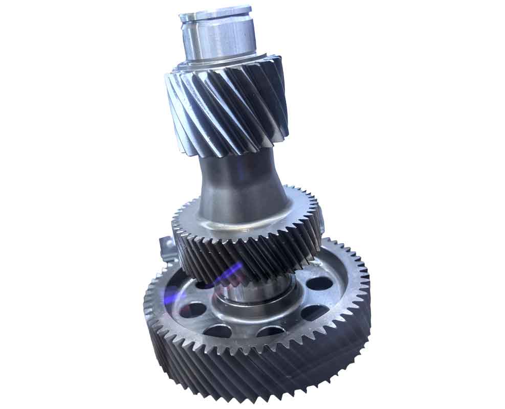
Reverse gear engineering provides indispensable solutions for reconstructing complex mechanical components when original design parameters are unavailable. This approach is particularly valuable for specialized components like curvic gears, which feature unique tooth geometry enabling high centering accuracy and exceptional load-bearing capacity across industrial and military applications. While traditional manufacturing processes for these gears are well-established, reverse gear reconstruction presents distinct challenges in parameter extraction and precision modeling. This article details a comprehensive methodology leveraging advanced reverse gear techniques to achieve accurate digital reconstruction of curvic couplings.

Curvic gears function primarily in couplings for torque transmission, offering superior self-centering and load distribution compared to conventional face gears. However, their complex curvature demands higher manufacturing precision, increasing production costs. The reverse gear process circumvents design documentation gaps through systematic hardware-to-software reconstruction.
Reverse Engineering Framework
Reverse gear methodology fundamentally inverts conventional design sequences by capturing physical geometry through 3D scanning and computationally rebuilding parametric models. Critical software platforms enabling this workflow include:
| Software | Developer | Key Capabilities |
|---|---|---|
| Geomagic DesignX | Raindrop Geomagic | Point cloud processing, parametric modeling, CAD integration |
| Imageware | EDS | Surface reconstruction, quality analysis |
| CopyCAD | DELCAM | Mesh editing, surface fitting |
| RapidForm | INUS Technology | Automated alignment, deviation analysis |
For curvic gear reconstruction, Geomagic DesignX provides optimal integration of reverse gear workflows with forward modeling capabilities essential for precision-critical applications.
Reverse Gear Reconstruction Process
Phase 1: Data Acquisition
3D scanning captures dense point clouds through laser triangulation, where reflected beams encode spatial coordinates according to:
$$P_{xyz} = \int_{t_0}^{t} \lambda \cdot \varphi(\theta,\phi) \,dt$$
where $P_{xyz}$ represents point coordinates, $\lambda$ is laser wavelength, and $\varphi$ denotes angular displacement. Simultaneously, physical measurements record gear parameters:
- Outer diameter ($D$)
- Tooth count ($N$)
Phase 2: Point Cloud Processing
Raw scan data undergoes noise reduction and smoothing algorithms before mesh conversion. Excessive smoothing degrades tooth profile accuracy – a critical consideration in reverse gear workflows. Optimized filtering balances defect removal with feature preservation.
Phase 3: Coordinate System Establishment
Precision in reverse gear modeling hinges on accurate axis determination. For rotary components, the central axis ($\vec{A}$) is derived from multiple cylindrical fits:
$$\vec{A} = \underset{\vec{a}}{\arg\min} \sum_{i=1}^{k} \left( \frac{\partial \epsilon_i}{\partial \vec{a}} \right)^2$$
where $\epsilon_i$ represents radial deviations of candidate surfaces. Selection of primary reference surfaces significantly impacts reconstruction fidelity.
Phase 4: Tooth Entity Reconstruction
Two reverse gear approaches rebuild teeth geometry:
- Individual tooth reconstruction (high accuracy, error accumulation)
- Pattern-based replication (time-efficient, axis-dependent)
Hybrid methodology samples multiple teeth (typically 6) at equiangular intervals. Comparative deviation analysis identifies the optimal master tooth for pattern replication, minimizing cumulative errors inherent in reverse gear processes.
Phase 5: Model Correction
Parametric validation against curvic gear design fundamentals enhances reverse gear accuracy. Critical geometric relationships include:
| Parameter | Equation | Variables |
|---|---|---|
| Face width | $b = 0.125D$ | $b$: width, $D$: outer diameter |
| Module | $m_{et} = \frac{D}{N + 1.5}$ | $m_{et}$: module, $N$: tooth count |
| Whole depth | $h_t = a \cdot m_{et}$ | $h_t$: depth, $a$: load factor |
| Addendum | $h_a = 0.5(h_t – c)$ | $h_a$: addendum, $c$: clearance |
Load-dependent coefficients distinguish reconstruction parameters:
- Heavy loading: $a = 0.88$, $c = 0.10m_{et}$, $c_f = 0.09m_{et}$
- Light loading: $a = 0.616$, $c = 0.07m_{et}$, $c_f = 0.063m_{et}$
Standard pressure angle ($\alpha_0 = 30^\circ$) further constrains model correction. Deviation analysis validates adjustments before full gear pattern replication.
Phase 6: Physical Validation
Manufactured prototypes undergo contact pattern verification through bearing tests. Minimum 70% contact area confirms successful reverse gear reconstruction. Iterative corrections refine tooth profiles when necessary.
Critical Implementation Factors
Successful reverse gear execution requires addressing two primary challenges:
- Coordinate System Precision: Reference surface selection must consider manufacturing datums and functional interfaces. Reverse gear accuracy diminishes with poor axis definition.
- Design Intent Reconciliation: Effective reverse gear methodology transcends physical replication by recovering theoretical design parameters from manufactured artifacts.
These reverse gear principles enable practical applications including legacy component reproduction and quality verification when original documentation is unavailable.
Conclusion
This structured reverse gear methodology enables accurate reconstruction of curvic gears through integrated 3D scanning, parametric modeling, and design-based correction. The process demonstrates particular efficacy in maintenance scenarios where original specifications are lost or obsolete. By combining physical measurement with computational geometry, reverse gear techniques bridge the gap between manufactured components and digital design environments, ensuring continued operability of precision torque transmission systems across critical industries.
