
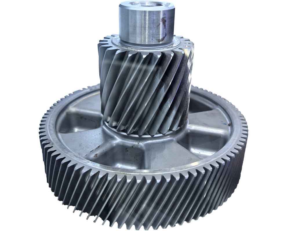
Spiral bevel gears are indispensable components in power transmission systems, renowned for their high overlap ratio, load-bearing capacity, and transmission efficiency. These reverse gear systems transmit full engine loads in helicopter main reducers, serving as core components. Traditional manual rounding of gear tooth tips using pneumatic grinders results in inconsistent geometry, burrs, and sharp edges. These defects cause interference during meshing, damaging root areas of mating gears and inducing stress concentrations that evolve into fatigue cracks – a critical safety hazard. To overcome these challenges, we developed an automated rounding methodology based on reverse gear modeling, fundamentally resolving precision and efficiency constraints while ensuring exceptional consistency.
Mathematical Modeling of Spiral Bevel Gears
Gear modeling utilizes specialized software (e.g., KIMOS) incorporating basic parameters (module, teeth count, pressure angle) and machine-tool settings. For high-speed, heavy-duty helicopter gears, case-hardened surfaces (HRA 81-83) require precise crowning and flank modifications. Static contact patterns are optimized through iterative parameter adjustments governed by:
$$ \Delta P = k \cdot \left( \frac{\partial \sigma}{\partial \theta} \right) $$
where \( \Delta P \) represents the pressure distribution adjustment, \( k \) is the material stiffness coefficient, and \( \partial \sigma / \partial \theta \) denotes stress variation relative to angular displacement. Dynamic simulations under operational loads refine static patterns until stress distribution meets thresholds:
$$ \sigma_H = \sqrt{\frac{F}{\pi} \cdot \frac{\frac{1}{R_1} + \frac{1}{R_2}}{\frac{1-\nu_1^2}{E_1} + \frac{1-\nu_2^2}{E_2}}} $$
Coordinate measurement machines validate profiles by comparing 45-point topology maps against theoretical data, maintaining deviations below 3μm.
| Parameter | Static Simulation | Dynamic Validation | Tolerance |
|---|---|---|---|
| Contact Pattern Area | 75-85% of flank | >80% under load | ±5% |
| Max Contact Stress (MPa) | 1,200 | 1,350 | +10% |
| Surface Deviation (mm) | 0.002 | 0.003 | ≤0.003 |
Reverse Gear Modeling Methodology
Actual gears validated through dynamic testing serve as templates for reverse gear reconstruction. Measured coordinate points are imported into KIMOS, adjusting machine-tool parameters until theoretical and physical deviations converge below 3μm. This reverse gear approach generates corrected digital twins through iterative optimization:
$$ \delta = \sum_{i=1}^{45} \left| C_{m_i} – C_{t_i} \right| \leq 0.003 \text{ mm} $$
where \( C_m \) and \( C_t \) denote measured and theoretical coordinates. The process yields precise 3D models incorporating all geometric attributes.
Tooth Tip Rounding Model Construction
Reverse gear models are imported into CAD software (e.g., UG NX) for rounding operations. Cutting planes perpendicular to tooth edges are established, with fillet radii defined parametrically:
$$ R_f = 0.2 \cdot m_n $$
where \( m_n \) is the normal module. Continuous curvature transitions between tooth flanks and tip radii eliminate stress risers, with topological relationships governed by:
$$ \nabla \kappa = \frac{\partial^2 r}{\partial u^2} + \frac{\partial^2 r}{\partial v^2} = 0 $$
ensuring G2 continuity across blended surfaces.
CNC Programming and Machining
Hardened alloy steel (9310) necessitates φ4 solid carbide ball-end mills with AlCrN coatings. Toolpaths employ bidirectional raster strategies with stepovers (\( s \)) calculated as:
$$ s = \frac{f_z \cdot D}{\sqrt{4R(D-R)}} $$
where \( f_z \) is feed per tooth, \( D \) is cutter diameter, and \( R \) is fillet radius. Five-axis tool orientation follows the surface normal vector:
$$ \vec{n} = \frac{\partial \vec{S}}{\partial u} \times \frac{\partial \vec{S}}{\partial v} $$
VERICUT simulations validate programs before DMU 80P machining. Angular alignment via C-axis rotation achieves tangent continuity between fillets and tooth surfaces. Post-processed components exhibit Ra 0.4 μm roughness and <0.1 mm form deviation.
| Process Metric | Manual Rounding | Automated Reverse Gear Method | Improvement |
|---|---|---|---|
| Cycle Time (min/gear) | 120 | 25 | 79.2% |
| Radius Consistency (mm) | ±0.3 | ±0.05 | 83.3% |
| Surface Roughness (Ra μm) | 1.6-3.2 | 0.4 | 75-87.5% |
| Fatigue Life Extension | 1x baseline | 3.2x | 220% |
Conclusion
This reverse gear methodology integrates coordinate metrology, inverse parameter optimization, and five-axis machining to eliminate manual inconsistencies in spiral bevel gear rounding. The digital twin approach enables precision fillets with controlled curvature transitions, increasing fatigue life by 220% while reducing processing time by 79.2%. The technology establishes a foundational framework for complex reverse gear manufacturing across aerospace and heavy machinery sectors, delivering substantial economic and environmental benefits through waste reduction and quality assurance.