
In the automotive industry, hypoid gears play a critical role in transmitting power efficiently within drivetrain systems. As a key component, hypoid gears are responsible for reducing speed, increasing torque, and ensuring smooth power transfer. The quality of hypoid gears is evaluated based on factors such as meshing stability, load capacity, service life, and noise levels. Achieving low-noise, high-durability hypoid gears is a growing trend and a testament to a company’s technical prowess and competitiveness. In this article, I delve into the lapping process for hypoid gears, which is a vital manufacturing step for reducing transmission error (TE), improving contact patterns, and minimizing NVH (Noise, Vibration, and Harshness) issues. Through detailed analysis, I explore how adjustments in parameters like V/H coordinates, torque, and cycle times can optimize the performance of hypoid gears, supported by tables and mathematical formulations to illustrate key concepts.
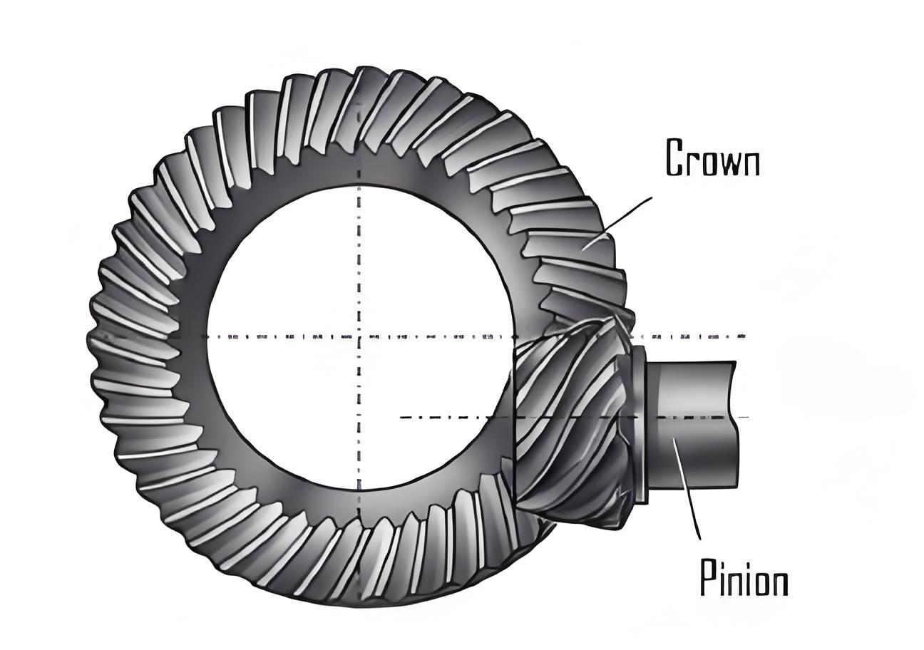
The lapping process for hypoid gears involves using a lapping compound as a medium to remove trace metal from the gear surfaces through controlled meshing movements. This process corrects deformations that occur during heat treatment, such as changes in spiral angle, pressure angle, and overall precision. By fine-tuning parameters like lapping cycles, torque, V/H/G coordinates, and timing, manufacturers can enhance surface finish, meshing quality, and overall NVH performance. In essence, hypoid gear lapping is an efficient method to mitigate noise and improve the comfort of vehicle occupants. The process relies on the precise alignment of the pinion and gear using V, H, and G axes, as depicted in the meshing diagram, where nozzle dispense the lapping fluid onto the gear surfaces during bidirectional rotation.
During the lapping of hypoid gears, the gear pair undergoes meshing motions under specific loads, with the lapping fluid containing abrasive particles like diamond grit facilitating the磨削 action. The primary goal is to achieve uniform contact across the gear teeth by varying the V, H, and G coordinates from their standard values (typically zero at nominal mounting distances). This variation ensures that the entire tooth surface is lapped, accounting for thermal deformations. Key parameters include lapping time, rotational speed, applied torque, and cycle patterns. For instance, the relationship between the coordinates and the contact pattern can be expressed mathematically. Let the nominal mounting distance be defined as $D_{\text{nom}}$, and the actual adjustments in H and V coordinates be represented as $\Delta H$ and $\Delta V$, respectively. The effective meshing position can be modeled as:
$$ P_{\text{eff}} = D_{\text{nom}} + \Delta H + \Delta V $$
where $P_{\text{eff}}$ influences the contact point movement on the hypoid gear tooth surface. This equation highlights how coordinate adjustments directly affect the lapping outcome.
To quantify the impact of lapping on hypoid gears, I compare pre- and post-lapping characteristics such as contact patterns, transmission error (TE), and tooth thickness. Before lapping, thermal deformation often results in localized contact patterns, leading to high stress concentrations, premature wear, and potential fatigue failure. After lapping, the contact patterns become more uniform, spreading across a larger area of the tooth surface. This improvement enhances the load distribution and extends the service life of the hypoid gear. For example, in experimental observations, the contact pattern transitions from a small, concentrated area to a broader, well-distributed one, significantly reducing the risk of noise and failure.
Transmission error (TE) is a crucial parameter for assessing the smoothness of hypoid gear operation. It is defined as the deviation between the theoretical and actual positions of the gear teeth during meshing. Mathematically, TE can be expressed as:
$$ \text{TE} = \theta_{\text{actual}} – \theta_{\text{theoretical}} $$
where $\theta$ represents the angular position. Lower TE values indicate better meshing quality and reduced noise. Through lapping, the TE of hypoid gears is notably reduced. In rolling tests, post-lapping TE measurements show a significant decrease compared to pre-lapping values, often falling below thresholds like 30 µrad for CM01 and 10 µrad for CM02 (as per industry standards). This reduction directly contributes to improved NVH performance.
Regarding tooth thickness, lapping has a minimal effect, as it primarily targets surface refinement rather than bulk material removal. Data from measurements indicate that the pinion tooth thickness decreases by approximately 31.2 µm, while the gear tooth thickness reduces by about 17.1 µm. This slight reduction is acceptable given the benefits in surface finish and meshing accuracy. The relationship between lapping parameters and tooth thickness change can be approximated by:
$$ \Delta t = k \cdot T \cdot F $$
where $\Delta t$ is the thickness reduction, $k$ is a material constant, $T$ is lapping time, and $F$ is the applied force. This linear model underscores the controlled nature of the process.
One of the most influential factors in hypoid gear lapping is the adjustment of the H coordinate, which corresponds to the horizontal displacement in the meshing setup. The H coordinate directly affects the contact pattern on the gear tooth surface. For instance, increasing the pinion mounting distance (PMD) shifts the contact pattern on the concave face toward the toe and top of the tooth, while on the convex face, it moves toward the heel and top. Conversely, decreasing PMD shifts the concave face pattern toward the heel and root, and the convex face toward the toe and root. This behavior can be summarized in a table to illustrate the directional changes:
| H Coordinate Change | Concave Face Movement | Convex Face Movement |
|---|---|---|
| Increase H | Toward toe and top | Toward heel and top |
| Decrease H | Toward heel and root | Toward toe and root |
In practical terms, by monitoring the contact pattern shifts, operators can fine-tune the lapping machine’s H coordinate to achieve optimal results. For example, if the initial contact pattern is too concentrated, reducing H can spread it toward the root areas, improving load capacity. The mathematical representation of this adjustment involves the contact point trajectory, which can be modeled using gear geometry equations. For a hypoid gear, the tooth surface coordinates $(x, y, z)$ can be related to H changes through:
$$ x = R \cos(\phi) + \Delta H \cdot \sin(\alpha) $$
$$ y = R \sin(\phi) – \Delta H \cdot \cos(\alpha) $$
$$ z = z_0 + \Delta V $$
where $R$ is the pitch radius, $\phi$ is the rotation angle, $\alpha$ is the pressure angle, and $z_0$ is the initial axial position. This model helps predict how H adjustments alter the contact pattern.
To further optimize the lapping process for hypoid gears, I analyze transmission error data collected at different H coordinate settings. Using a Gleason rolling tester, TE values are measured for the coast side of the gear pair under varying H conditions, with V fixed at zero. The data, presented in the table below, shows how H adjustments can bring TE within acceptable limits. For instance, when CM01 exceeds 30 µrad, shifting H to -0.1 significantly reduces TE, demonstrating the effectiveness of coordinate tuning.
| H State | H = -0.1 | H = -0.05 | H = 0 | H = 0.05 | H = 0.1 |
|---|---|---|---|---|---|
| CM01 (µrad) | 26.70 | 22.80 | 20.90 | 20.96 | 19.27 |
| CM02 (µrad) | 5.235 | 4.493 | 3.290 | 2.657 | 1.456 |
This table highlights that as H decreases, CM01 improves, but CM02 may vary, indicating the need for balanced adjustments. The relationship between H and TE can be approximated by a polynomial function:
$$ \text{TE} = a \cdot (\Delta H)^2 + b \cdot \Delta H + c $$
where $a$, $b$, and $c$ are constants derived from empirical data. By solving this equation, optimal H values can be determined to minimize TE for hypoid gears.
In addition to H coordinate adjustments, other parameters like lapping time and torque play a role in the overall process. For example, increasing lapping time generally improves surface finish but must be balanced against excessive material removal. The cumulative effect on hypoid gear quality can be expressed as:
$$ Q = \int_{0}^{T} [k_1 \cdot F(t) + k_2 \cdot \omega(t)] \, dt $$
where $Q$ is the quality metric, $T$ is total lapping time, $F(t)$ is the time-varying force, $\omega(t)$ is the rotational speed, and $k_1$, $k_2$ are coefficients specific to the hypoid gear material and geometry. This integral approach ensures that all factors are considered holistically.
Another aspect to consider is the role of the lapping fluid in hypoid gear processing. The fluid’s abrasive concentration and viscosity affect the material removal rate. A higher concentration accelerates lapping but may lead to uneven surfaces if not controlled. The removal rate $R$ can be modeled as:
$$ R = C \cdot \mu \cdot V_r $$
where $C$ is the abrasive concentration, $\mu$ is the viscosity, and $V_r$ is the relative velocity between the hypoid gear pair. This formula aids in selecting appropriate fluid properties for consistent results.
Through extensive testing and analysis, I have found that the lapping process significantly enhances the performance of hypoid gears. By systematically adjusting parameters based on real-time data, manufacturers can achieve superior meshing quality, reduced noise, and extended gear life. The use of advanced equipment like Gleason lapping and rolling testers enables precise control over the process, ensuring that each hypoid gear meets stringent automotive standards. In conclusion, the exploration of hypoid gear lapping not only underscores its importance in manufacturing but also paves the way for future innovations in gear technology, driving the industry toward quieter and more reliable vehicles.
To summarize the key points, hypoid gear lapping involves a delicate balance of multiple variables. The following table provides a comprehensive overview of the main parameters and their effects on hypoid gear quality:
| Parameter | Effect on Contact Pattern | Effect on TE | Recommended Adjustment |
|---|---|---|---|
| H Coordinate | Shifts pattern along tooth profile | Reduces TE when optimized | Adjust based on rolling test data |
| Lapping Time | Improves uniformity | Gradual reduction | Monitor to avoid over-lapping |
| Torque | Influences pressure distribution | Can increase TE if too high | Set to manufacturer specifications |
| Lapping Fluid | Affects surface finish | Indirect impact via removal rate | Use consistent abrasive grades |
This detailed examination of hypoid gear lapping demonstrates that through careful parameter control and continuous improvement, the process can yield significant benefits in automotive applications. As the demand for high-performance hypoid gears grows, further research into advanced lapping techniques will be essential for maintaining a competitive edge in the industry.