
In industrial applications, planetary gear systems are critical components in reducers due to their high efficiency, compact design, and ability to handle large transmission ratios. However, these systems often operate under harsh conditions where cyclic and impact loads are prevalent, leading to surface fatigue and pitting failures on gear teeth. The presence of impact loads introduces significant fluctuations in vibration signals, which can mask fault-related features and complicate diagnostic efforts. This study addresses this challenge by developing a diagnostic index based on the dynamic characteristics of planetary gear systems with pitting faults under impact conditions. We focus on modeling the contact behavior between sun gears and planet gears, incorporating impact loads, and proposing a novel energy-based metric for fault assessment. Through dynamic simulations and experimental validation, we demonstrate the effectiveness of our approach in distinguishing fault severity despite the干扰 of impact loads.
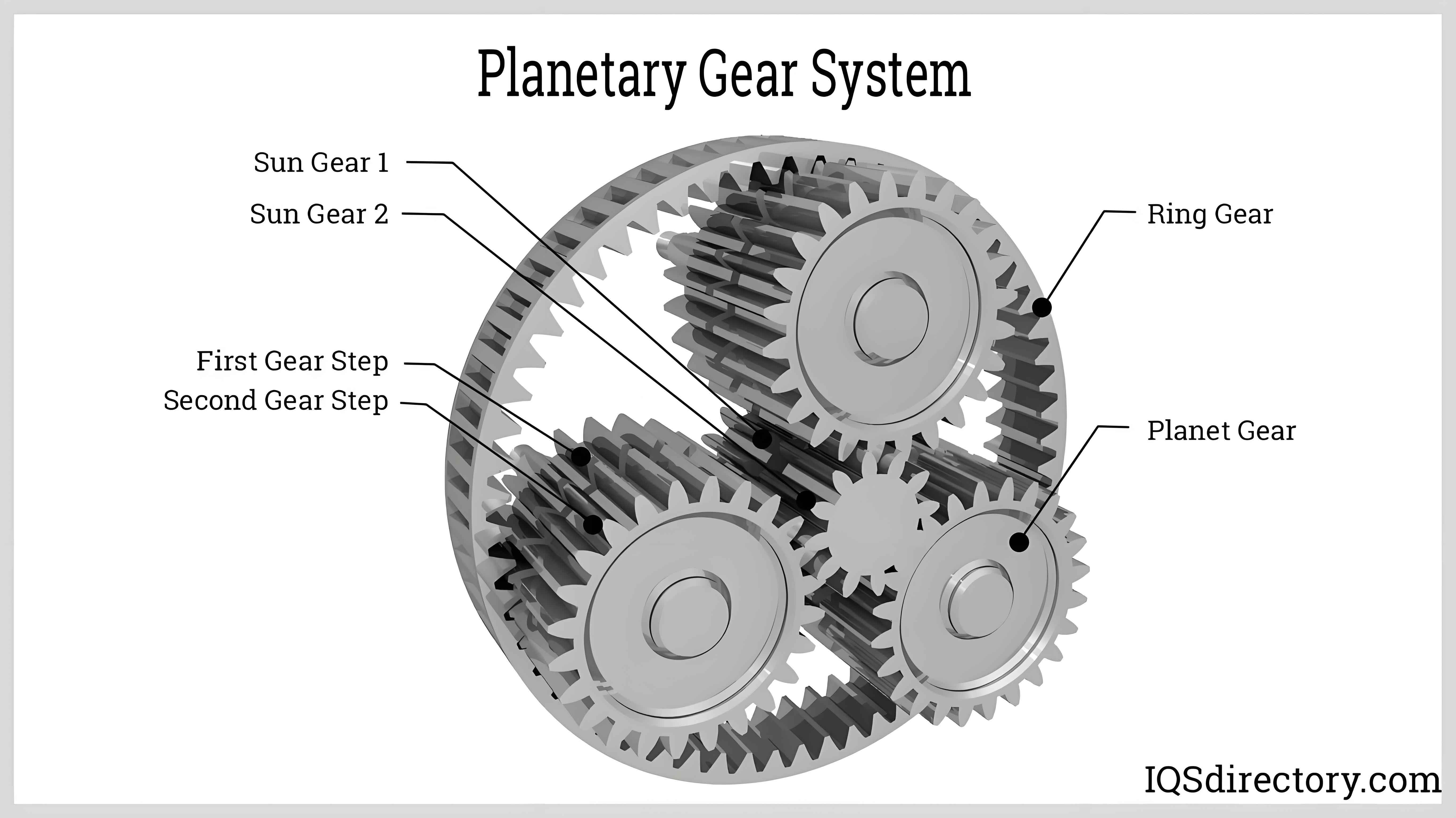
Planetary gear systems consist of a central sun gear, multiple planet gears mounted on a carrier, and an outer ring gear. The planet gears play a pivotal role in distributing loads and ensuring smooth torque transmission. Under impact conditions, the dynamic response of these systems becomes highly nonlinear, with increased vibration amplitudes and modulated frequency components. Pitting faults, which initiate as small surface cracks and evolve into localized cavities, alter the gear mesh stiffness and exacerbate vibrations. Traditional time-domain statistical indicators, such as root mean square (RMS) and kurtosis, often fail under impact loads due to signal non-stationarity. Therefore, we propose a frequency-domain approach that leverages the spectral distribution of dynamic responses to quantify fault severity.
Theoretical analysis begins with the calculation of meshing forces between the sun gear and planet gears. Using Hertzian contact theory and the impact function method, we model the gear pair interaction. The normal contact force \( F_n(t) \) is expressed as:
$$F_n(t) = K(t) \delta + \text{step}(\delta, 0, 0, d, c) \frac{d\delta}{dt}$$
where \( K(t) \) is the time-varying contact stiffness coefficient, \( \delta \) is the compression deformation depth at the contact point, \( d \) is the maximum allowable penetration depth, and \( c \) is the elastic damping coefficient. The step function ensures a smooth transition during contact initiation and separation. For pitting faults, the effective meshing force is modified to account for the reduced contact area:
$$F(t) = \frac{n L(t)}{2b} F_n(t)$$
Here, \( n \) is the number of contacting gear pairs, \( L(t) \) is the length of the line of action, and \( b \) is the tooth width. The contact stiffness coefficient \( K(t) \) is derived from Hertzian theory:
$$K(t) = \frac{4}{3} R^{1/2}(t) E$$
where \( R(t) \) is the composite radius of curvature and \( E \) is the composite elastic modulus. The composite radius \( R(t) \) for involute gears is given by:
$$\frac{1}{R(t)} = \frac{1}{R_1(t)} + \frac{1}{R_2(t)}$$
with \( R_i(t) = r_{b_i} \tan \alpha(t) \) for \( i = 1, 2 \), where \( r_{b_i} \) is the base circle radius and \( \alpha(t) \) is the pressure angle at the contact point. The composite elastic modulus \( E \) is calculated as:
$$\frac{1}{E} = \frac{1 – \nu_1^2}{E_1} + \frac{1 – \nu_2^2}{E_2}$$
where \( \nu_1, \nu_2 \) are Poisson’s ratios and \( E_1, E_2 \) are elastic moduli of the gear materials. The compression depth \( \delta(t) \) is related to the normal load \( p(t) \) by:
$$\delta(t) = \left[ \frac{9p^2(t)}{16 R(t) E^2} \right]^{1/3}$$
To model pitting faults, we consider the distribution of loads along the line of action. The gear contact ratio \( \epsilon \) is:
$$\epsilon = \frac{z_1 (\tan \alpha_{a1} – \tan \alpha) + z_2 (\tan \alpha_{a2} – \tan \alpha)}{2\pi}$$
where \( z_1, z_2 \) are the numbers of teeth on the sun gear and planet gears, and \( \alpha_{a1}, \alpha_{a2} \) are the tip pressure angles. For a pitting defect located at a radius \( r_e(t) \) on the sun gear, the distance between two points on the faulted tooth profile is:
$$d(t) = \sqrt{r_e^2(t) + r_1^2 – 2 r_e(t) r_1 \cos(\omega_1 t – \alpha)}$$
where \( \omega_1 \) is the angular velocity of the sun gear. The length of the defect on the line of action is approximated as:
$$l(t) = \sqrt{ \left( \frac{D}{2} \right)^2 – \left[ \frac{D}{2} – d(t) \right]^2 }$$
with \( D \) being the maximum diameter of the pitting cavity. The effective line of action length \( L(t) \) varies with the meshing phase: during double-tooth contact without defects, \( L(t) = 2b \); during single-tooth contact with pitting, \( L(t) = b – N l(t) \), where \( N \) is the number of pits. In cases where pits are present during double-tooth contact, \( L(t) = 2b – N l(t) \). This formulation allows us to simulate different fault severities by varying \( N \), as summarized in Table 1.
| Parameter | Symbol | Value |
|---|---|---|
| Sun gear teeth | \( z_1 \) | 21 |
| Planet gear teeth | \( z_2 \) | 31 |
| Ring gear teeth | \( z_3 \) | 84 |
| Module (mm) | \( m \) | 2 |
| Pressure angle (°) | \( \alpha \) | 20 |
| Pitting severity levels | \( N \) | 5 (mild), 10 (moderate), 15 (severe) |
| Base circle radius, sun (mm) | \( r_{b1} \) | 19.7 |
| Base circle radius, planet (mm) | \( r_{b2} \) | 29.1 |
Dynamic simulations were conducted using a multibody dynamics approach. The planetary gear model included a sun gear rotating at 1000 rpm, with the carrier speed set to 200 rpm based on the transmission ratio. The contact stiffness coefficient \( K \) was calculated as \( 3.0459 \times 10^5 \, \text{N/mm}^{3/2} \), with a material collision coefficient of 1.5, damping coefficient at 0.1% of stiffness, and penetration depth of 0.1 mm. Friction was modeled using Coulomb’s law, with static and dynamic friction coefficients of 0.08 and 0.05, respectively. The simulation time was 10 seconds with 100,000 steps to ensure accuracy.
Under impact loads, applied as pulse torques on the carrier, the meshing forces between the sun gear and planet gears exhibited significant fluctuations. Figure 1 shows the time-domain response of the radial meshing force without and with impact loads. In the absence of impacts, the force oscillates periodically with a meshing period of 0.0036 s, corresponding to the meshing frequency. Impact loads introduce transient peaks that increase with load magnitude, leading to broader frequency spectra with sidebands around the meshing frequency, as illustrated in Figure 2. These sidebands result from the modulation of the meshing frequency by low-frequency components associated with impact events.
For pitting faults, the dynamic response shows periodic spikes corresponding to the fault engagement frequency. The time interval between successive fault impacts is 0.025 s, equivalent to a characteristic frequency of 40 Hz. In the frequency domain, the meshing frequency (e.g., 280 Hz) is flanked by sidebands spaced at 40 Hz intervals, indicating modulation by the fault frequency. Additionally, sidebands at the carrier rotational frequency (3.4 Hz) appear around the sun gear relative rotational harmonics. As fault severity increases, the amplitude and bandwidth of these sidebands expand, providing a basis for fault quantification.
To reliably assess fault severity under impact conditions, we propose the sideband centroid energy index \( SC \), defined as:
$$SC = \frac{ \sum_{n = \text{max} – f_s}^{\text{max} + f_s} f(n) \cdot E(n) }{ \sum_{n = \text{max} – f_s}^{\text{max} + f_s} E(n) }$$
where \( f(n) \) is the frequency value, \( E(n) \) is the spectral energy at frequency bin \( n \), \( \text{max} \) is the meshing frequency, and \( f_s \) is the fault characteristic frequency. This index captures the energy distribution in the sideband regions and is less sensitive to impact-induced noise. Simulations for mild, moderate, and severe pitting faults under impact loads reveal that \( SC \) increases monotonically with fault severity, as shown in Table 2. The consistency of \( SC \) across different impact levels demonstrates its robustness for fault diagnosis.
| Fault Severity | Number of Pits \( N \) | Sideband Centroid Energy \( SC \) |
|---|---|---|
| Mild | 5 | 285.3 |
| Moderate | 10 | 312.7 |
| Severe | 15 | 349.8 |
Experimental validation was performed on a 2K-H planetary gearbox test rig. The setup included an electric motor, coupling, planetary gearbox, tri-axial vibration sensors, encoder, and a magnetic powder brake for applying impact loads. The sun gear had 21 teeth, each planet gear had 31 teeth, and the ring gear had 84 teeth, with a module of 2 mm. Vibration data were acquired at a sampling rate of 61,440 Hz for 307,200 points. Pitting faults were simulated by laser-etching circular pits on the sun gear tooth flanks near the pitch line, with 5, 10, and 15 pits representing mild, moderate, and severe faults, respectively.
Time-domain acceleration signals showed increased amplitude fluctuations with fault severity, from 2.5 m/s² for mild faults to 3.8 m/s² for severe faults under impact loads. The fault-induced impacts were distinguishable from mesh impacts by their higher amplitude and periodicity. Frequency-domain analysis confirmed the presence of sidebands around the meshing frequency at intervals of the fault frequency (39.8 Hz) and carrier frequency (3.4 Hz). The \( SC \) index was computed for each fault condition, with results summarized in Table 3. Comparative analysis of traditional indicators like RMS, kurtosis, and shape factor showed poor discrimination between fault levels, whereas \( SC \) provided clear separation, affirming its diagnostic value.
| Fault Severity | RMS (m/s²) | Kurtosis | Shape Factor | Sideband Centroid Energy \( SC \) |
|---|---|---|---|---|
| Mild | 1.2 | 3.5 | 1.1 | 290.1 |
| Moderate | 1.3 | 3.6 | 1.2 | 315.4 |
| Severe | 1.5 | 3.7 | 1.3 | 352.9 |
In conclusion, this study presents a comprehensive method for evaluating pitting faults in planetary gear systems under impact conditions. By integrating Hertzian contact theory, dynamic simulation, and spectral analysis, we have shown that impact loads exacerbate vibration responses but can be accounted for through the proposed sideband centroid energy index. The planet gears are central to this analysis, as their interactions with the sun gear dictate the system’s dynamic behavior. The \( SC \) index effectively quantifies fault severity despite the presence of impact loads, offering a reliable tool for condition monitoring. Future work could extend this approach to helical gears or incorporate real-time signal processing for online diagnostics.
The robustness of our method stems from its focus on frequency-domain features that are inherently less affected by transient impacts. As industrial machinery continues to face demanding operating conditions, such diagnostic techniques will be crucial for preventing catastrophic failures and minimizing downtime. We emphasize the importance of accurate contact modeling and dynamic simulation in understanding the complex behavior of planetary gear systems, particularly when planet gears are subject to simultaneous fault and impact excitations.