
In modern manufacturing, industries such as automotive and aerospace demand components that optimize space and minimize weight while maintaining high strength and performance. Bevel gears play a critical role in these applications, enabling efficient power transmission between intersecting shafts. Their complex geometry, which includes conical shapes and angled teeth, presents significant challenges in machining, particularly for single-piece production where precision and efficiency are paramount. The material properties of aluminum alloys, such as LY12, offer advantages like good plasticity and high strength-to-weight ratio, but they also introduce issues like tool adhesion and deformation during processing. This paper explores the machining process for a servo bevel gear housing, addressing key aspects like tool selection, cutting parameters, and fixture design to achieve high precision in single-piece manufacturing. The integration of CAD/CAM software and multi-axis CNC machining is emphasized to overcome difficulties such as irregular shapes, thin-walled structures, and stringent tolerance requirements. Through experimental validation and simulation, optimal strategies are developed to enhance the machining of bevel gears, ensuring dimensional accuracy and structural integrity.
The characteristics of bevel gears necessitate a detailed dimensional analysis to ensure proper functionality in assemblies. Bevel gears typically feature conical surfaces with teeth that are cut along an angle, requiring precise control over parameters like pitch angle, root angle, and face width. For instance, a representative bevel gear housing might include critical dimensions such as the shaft intersection angle, which is often 90 degrees but can vary, and the gear ratio determined by the number of teeth. Key tolerances include the backlash between mating gears, which affects noise and efficiency, and the concentricity of bores for shaft mounting. In this analysis, the focus is on a bevel gear housing with a shaft angle of 90 degrees and a module of 2.5, where the pitch diameter is given by $$ D_p = m \times z $$ where \( m \) is the module and \( z \) is the number of teeth. The tooth depth \( h \) can be calculated as $$ h = 2.25 \times m $$ ensuring proper meshing. Tolerances for these dimensions are tight, often within ±0.02 mm, to prevent issues like misalignment and wear. The housing may also include mounting flanges and bolt circles, with positional tolerances critical for assembly. For example, the bore for the bevel gear shaft must have a diameter of φ50H7 with a concentricity tolerance of 0.01 mm relative to the mounting face. Such precision demands advanced machining techniques to avoid errors that could compromise the performance of bevel gears in applications like differential systems or power tools.
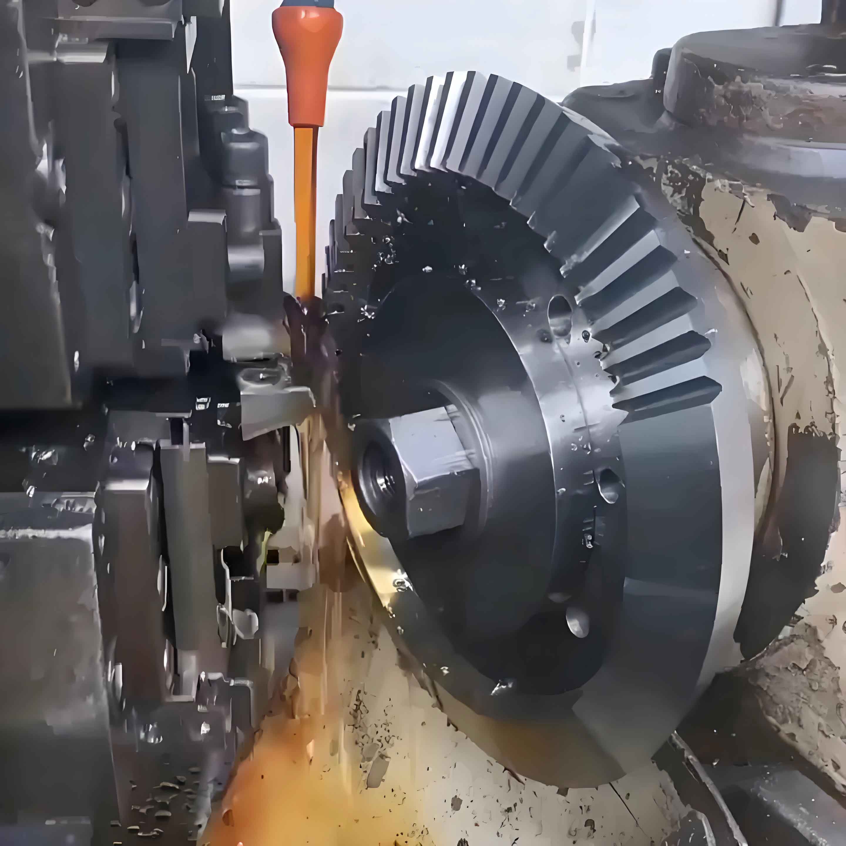
Machining bevel gears involves several difficulties that stem from their geometric complexity and material behavior. One primary challenge is the irregular shape of bevel gear teeth, which are not uniform like spur gears but taper along the cone, making tool paths complex and prone to errors. The thin-walled sections near the gear rim can lead to deformation during cutting due to low rigidity, resulting in vibrations and poor surface finish. Additionally, the high hardness of materials like LY12 aluminum, with a typical hardness of HB90-95 after heat treatment, causes rapid tool wear and adhesion, further complicating the process. Another issue is the precise control of tooth profile and spacing, which requires multi-axis machining to maintain the correct pressure angle and helix angle. The pressure angle \( \alpha \) for bevel gears is typically 20 degrees, and the spiral angle \( \beta \) might range from 0 to 35 degrees, calculated as $$ \tan \beta = \frac{\pi D_p}{L} $$ where \( L \) is the face width. Fixturing is also problematic because the conical shape makes it difficult to clamp without inducing stress or distortion, especially in single-piece production where custom fixtures are needed. These factors collectively increase the risk of dimensional inaccuracies, such as errors in tooth thickness or pitch, which can exceed allowable limits and render the bevel gears unusable. Therefore, addressing these machining difficulties requires a holistic approach involving optimized tool geometry, dynamic cutting parameters, and robust fixture designs.
To address the machining challenges of bevel gears, a comprehensive machining scheme is developed, focusing on multi-axis CNC operations to handle the complex geometry. The process begins with a rough machining phase on a 3-axis vertical machining center, where a rectangular LY12 aluminum block of dimensions 200mm × 150mm × 100mm is used as the raw material. This phase removes bulk material and establishes basic shapes, leaving allowances of 0.5 mm for finishing. Subsequently, the part is transferred to a 4-axis machine with a rotary table, where the bevel gear teeth and housing features are finished. The rotary table allows for continuous indexing, enabling the machining of angled surfaces and teeth in a single setup to maintain accuracy. For the bevel gear teeth, a specific tool path is generated using CAM software, incorporating trochoidal milling strategies to reduce cutting forces and minimize deformation. The cutting speed \( V_c \) and feed per tooth \( f_z \) are critical parameters, derived from the formula $$ V_c = \frac{\pi D n}{1000} $$ where \( D \) is the tool diameter and \( n \) is the spindle speed. A typical set of parameters for roughing includes a spindle speed of 2000 rpm and a feed rate of 500 mm/min, while finishing uses higher speeds up to 3000 rpm and lower feeds of 100 mm/min to achieve a surface roughness Ra ≤ 1.6 μm. To ensure the bevel gears meet specifications, the scheme also includes a semi-finishing step where teeth are cut with a ball-nose end mill, followed by a finishing pass with a dedicated bevel gear cutter. This approach reduces the need for multiple setups, minimizing cumulative errors and enhancing the precision of the bevel gears’ tooth profiles and mounting surfaces.
| Machining Operation | Tool Type | Spindle Speed (rpm) | Feed Rate (mm/min) | Depth of Cut (mm) |
|---|---|---|---|---|
| Roughing | Flat End Mill | 2000 | 500 | 2.0 |
| Semi-Finishing | Ball-Nose End Mill | 2500 | 200 | 0.5 |
| Finishing | Bevel Gear Cutter | 3000 | 100 | 0.1 |
Fixture design is crucial for maintaining the accuracy of bevel gears during machining, as improper clamping can lead to deformation and misalignment. For the bevel gear housing, a custom fixture is developed using a mandrel that fits into the bore of the gear, providing radial support and axial positioning. The mandrel is made from hardened steel with a diameter of φ50h6 to match the housing bore of φ50H7, ensuring a slip fit with minimal clearance. This design allows the bevel gear to be mounted on a 4-axis rotary table, where the mandrel acts as a datum for machining the teeth and other features. The positioning error is analyzed using the synthesis method, where the total error \( \Delta_D \) is the sum of the基准位移误差 \( \Delta_Y \) and the基准不重合误差 \( \Delta_B \), expressed as $$ \Delta_D = \Delta_Y + \Delta_B $$. In this case, since the design基准 and process基准 coincide for the bore, \( \Delta_B = 0 \). The displacement error \( \Delta_Y \) arises from the fit between the mandrel and the bore, calculated as $$ \Delta_Y = \frac{\delta_D}{2} + \frac{\delta_d}{2} $$ where \( \delta_D \) is the tolerance of the bore (0.025 mm for H7) and \( \delta_d \) is the tolerance of the mandrel (0.013 mm for h6). Thus, \( \Delta_Y = \frac{0.025}{2} + \frac{0.013}{2} = 0.019 \) mm, which is less than one-third of the part tolerance (e.g., 0.05 mm), ensuring acceptable accuracy. The fixture also includes a clamping mechanism that applies uniform pressure on the gear face to prevent distortion, and it is calibrated on the machine before processing to eliminate runout. This approach minimizes errors in the bevel gears’ tooth alignment and concentricity, which are vital for smooth operation in applications like automotive differentials.
The machining of bevel gears presents specific difficulties in achieving the required tooth geometry and surface quality. One major challenge is the control of the tooth flank, which must conform to a predefined profile to ensure proper meshing with the mating gear. This involves generating the correct tooth trace and pressure angle, which for straight bevel gears can be described by the Gleason system, where the tooth depth varies along the face width. The formula for the chordal tooth thickness \( s_c \) at the large end is $$ s_c = m \times \frac{\pi}{2} $$ and it must be maintained within ±0.02 mm to avoid excessive backlash. During cutting, vibrations can occur due to the intermittent engagement of the tool with the angled teeth, leading to chatter marks and reduced accuracy. To mitigate this, dynamic cutting parameters are used, such as varying the spindle speed based on the formula $$ n = \frac{V_c \times 1000}{\pi D} $$ where \( V_c \) is optimized to 150 m/min for aluminum. Another issue is the burr formation at the tooth edges, which requires deburring operations that can add time and cost. For the bevel gears in this study, a finishing process with a specialized cutter is employed, using climb milling to reduce burrs and improve surface finish. The tool path is simulated in CAM software to avoid collisions and ensure continuous material removal, with the cutting force \( F_c \) estimated as $$ F_c = k_c \times a_p \times f $$ where \( k_c \) is the specific cutting force (e.g., 1000 N/mm² for aluminum), \( a_p \) is the depth of cut, and \( f \) is the feed per tooth. By optimizing these factors, the machining of bevel gears achieves a tooth profile error of less than 0.03 mm and a surface roughness of Ra 0.8 μm, meeting the demands for high-performance applications.
The results of machining the bevel gear housing are evaluated through coordinate measuring machine (CMM) inspections, focusing on critical dimensions and tolerances. Key parameters include the shaft bore diameters, tooth thickness, and concentricity, which are measured at multiple points to ensure consistency. For example, the bore for the bevel gear shaft is specified as φ50H7, with a tolerance range of 0 to +0.025 mm, and the measured values average φ50.012 mm, well within the limit. The tooth thickness at the pitch circle is designed to be 3.927 mm with a tolerance of ±0.02 mm, and the CMM data shows an average of 3.935 mm, indicating minimal deviation. The concentricity of the bore relative to the mounting face is required to be within 0.01 mm, and the measurements report a maximum deviation of 0.008 mm, demonstrating the effectiveness of the fixture and machining strategy. Additionally, the surface roughness of the tooth flanks is assessed using a profilometer, yielding Ra values between 0.7 and 1.0 μm, which satisfies the requirement for smooth operation. The table below summarizes the results for major dimensions, confirming that all are within specified tolerances and validating the process for single-piece production of bevel gears. This success highlights the importance of integrated process planning and parameter optimization in overcoming the inherent challenges of machining complex components like bevel gears.
| Dimension | Specification | Measured Value | Status |
|---|---|---|---|
| Shaft Bore Diameter | φ50H7 (0 to +0.025) | φ50.012 | Within Tolerance |
| Tooth Thickness | 3.927 ± 0.02 mm | 3.935 mm | Within Tolerance |
| Concentricity | ≤ 0.01 mm | 0.008 mm | Within Tolerance |
| Surface Roughness | Ra ≤ 1.6 μm | Ra 0.8 μm | Within Tolerance |
In conclusion, the single-piece machining of bevel gears requires a meticulous approach that addresses geometric complexity, material properties, and precision requirements. Through this analysis, I have demonstrated that multi-axis CNC machining, combined with optimized tool paths and cutting parameters, can effectively produce bevel gears with high dimensional accuracy and surface quality. The use of custom fixtures, such as mandrels, minimizes positioning errors and deformation, while CAM software enables efficient programming and simulation to avoid errors. The experimental results confirm that the proposed method achieves tolerances within acceptable limits, making it suitable for low-volume production of bevel gears in critical applications. Future work could involve finite element analysis to predict and mitigate machining-induced stresses, further enhancing the process. Overall, this study provides a practical framework for machining bevel gears, emphasizing the integration of technology and工艺 to meet the evolving demands of industries like automotive and aerospace.