
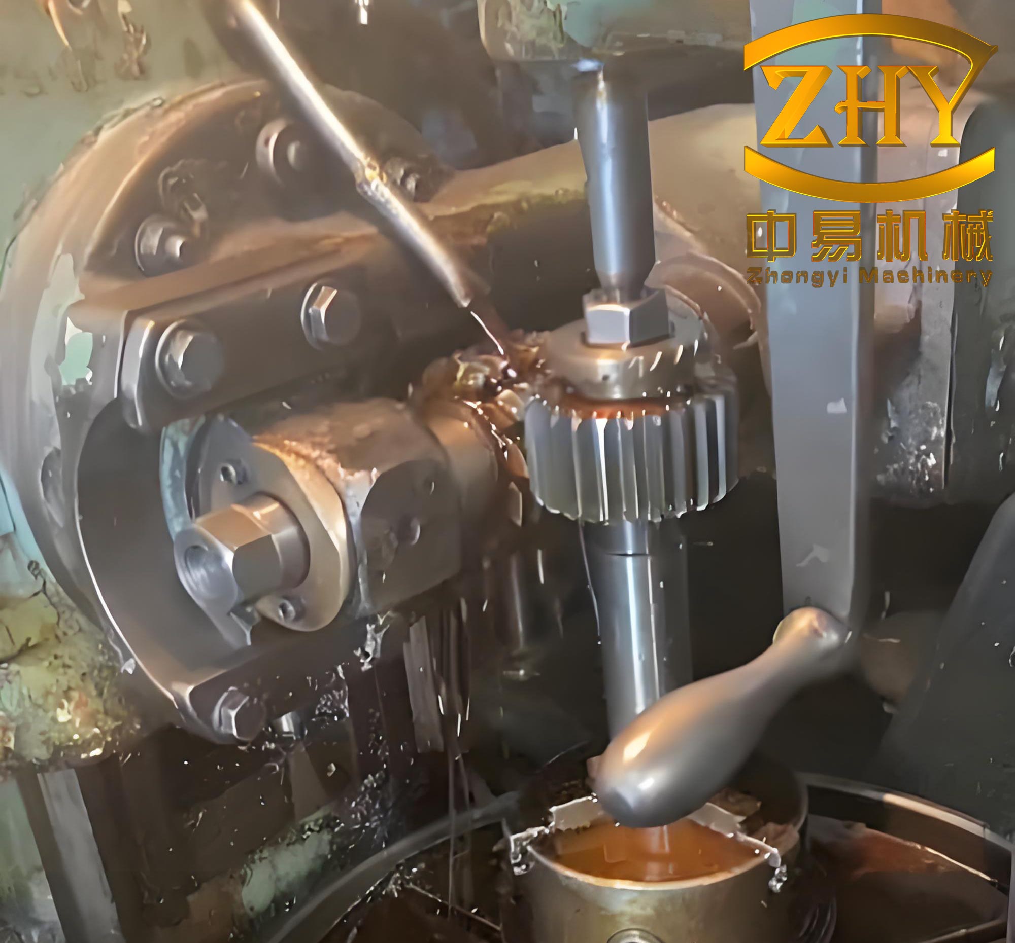
In the field of precision gear manufacturing for RV reducers, planetary gears play a critical role due to their complex structure involving both internal and external teeth. As a manufacturing engineer specializing in gear production, I have encountered numerous challenges in achieving high positional accuracy between these teeth during mass production. Gear hobbing has emerged as a preferred method over gear grinding in many scenarios due to its efficiency and evolving precision capabilities. This article delves into two typical anomalies—angular phase fluctuation and eccentricity—observed during the trial production of planetary gears using gear hobbing machines, and presents theoretical analyses and practical solutions backed by extensive process validation.
Gear hobbing, a form of generating machining, involves a gear hobbing machine equipped with a FANUC system and gear search functionality to precisely cut external teeth. While gear grinding allows for tooth profile modification and achieves high accuracy, it suffers from low efficiency. In contrast, gear hobbing compensates for this inefficiency, with the tooth profile controlled by the hob cutter’s shape. Advances in gear manufacturing have enabled gear hobbing to reach precision levels comparable to grinding. For planetary gears in RV reducers, where external tooth accuracy requirements are not excessively high, gear hobbing is adopted for its productivity benefits. However, maintaining the angular relationship and concentricity between internal and external teeth remains a hurdle. Through first-hand experience, I will elaborate on the root causes and remedies for these issues, incorporating mathematical models and tabular summaries to enhance clarity.
Angular Phase Fluctuation in Internal and External Teeth
During the gear hobbing of planetary gears, one prevalent issue is the significant fluctuation in the angular phase between internal and external teeth. The angular phase, denoted as α, is defined as the angle formed by the line connecting the midpoint of an internal tooth slot (point a), the gear center (point o), and the midpoint of an external tooth (point b). In ideal conditions, α should remain constant within a tight tolerance, but post-hobbing measurements often reveal variations up to ±0.1°, leading to low yield rates. This deviation adversely affects the RV reducer’s transmission error, load distribution, wear, noise, and lifespan.
To address this, I first analyzed the gear hobbing process on a high-precision gear hobbing machine. The machine’s C-axis is typically adjusted to compensate for angular errors by altering the cutting amount on the left and right flanks of the external teeth. This compensation is converted into a chordal length value, which corresponds to the material removal on one side of the tooth thickness. The theoretical basis for this involves calculating the pitch circle radius of the external teeth. The pitch circle radius \( r’ \) is derived as follows:
$$ r’ = r \cdot \frac{a’}{a} $$
where \( r \) is the reference circle radius, \( a’ \) is the actual center distance during hobbing (obtained from machine coordinates), and \( a \) is the theoretical center distance. The reference circle radius \( r \) is given by:
$$ r = \frac{m \cdot z}{2} $$
Here, \( m \) represents the module of the external teeth, and \( z \) is the number of teeth. The actual center distance \( a’ \) depends on the gear hobbing machine setup and hob radius \( r_{\text{hob}} \).
Through empirical measurements, I identified that insufficient hobbing allowance on the semi-finished planetary gear’s external teeth was a primary cause. Specifically, the single-side tooth thickness allowance was only about 0.05 mm, whereas the angular phase tolerance required an allowance of approximately 0.3 mm. This inadequacy led to non-contact between the hob and one tooth flank, causing deviations in the angular phase. Additionally, the gear search function of the gear hobbing machine, which determines the relative position between the hob tooth and the external tooth slot before each hobbing cycle, introduced errors due to variations in semi-finished gear quality. These search errors compounded when compensating the C-axis based on previous parts, resulting in unpredictable angular phase fluctuations.
To resolve this, I implemented a two-step solution. First, I increased the hobbing allowance on the external teeth to ensure full contact and elimination of non-illuminated tooth flanks. Second, I modified the hobbing sequence: only the first gear undergoes the search function, and after compensating the C-axis chordal length based on its angular phase measurement, the search function is disabled for subsequent batches. This approach minimizes search-induced errors and stabilizes the angular phase. The chordal compensation value \( C \) is calculated using trigonometric relations:
$$ C = 2 \cdot r’ \cdot \sin\left(\frac{\Delta \alpha}{2}\right) $$
where \( \Delta \alpha \) is the angular deviation. The following table summarizes the key parameters and their effects on angular phase control:
| Parameter | Description | Optimal Value/Range |
|---|---|---|
| Hobbing Allowance | Single-side tooth thickness for external teeth | 0.3 mm |
| Chordal Compensation (C) | Adjustment for angular phase correction | Based on \( \Delta \alpha \) and \( r’ \) |
| Gear Search Function | Machine feature for positioning | Enabled only for first piece |
This strategy significantly reduced angular phase fluctuations, improving yield rates in batch trials. The gear hobbing machine’s robustness was crucial in maintaining consistency, and repeated validations confirmed the effectiveness of these measures.
Eccentricity Between Internal and External Teeth
Another critical anomaly in planetary gear hobbing is excessive eccentricity, evaluated as radial runout (Fr) between the internal and external teeth. Measurements often showed Fr values ranging from 0.05 mm to 0.08 mm, far exceeding the precision requirements for RV reducers. This misalignment degrades the gear’s meshing performance, leading to increased noise and reduced service life.
My investigation began with verifying the gear hobbing machine’s condition. Checks on the machine base and pressure head revealed roundness and face runouts within 0.005 mm, indicating that the equipment was not the primary contributor. Instead, I focused on the hobbing fixture, which initially used a cylindrical spline that engaged with the internal teeth. The fit between the planetary gear’s internal teeth and this fixture was loose, as determined by measuring the base tangent length (public law line length) of both components. For a standard spur gear, the base tangent length \( W_k \) is calculated as:
$$ W_k = \cos \alpha \left[ \pi (k – 0.5) + z \cdot \text{inv} \alpha \right] m $$
where \( \alpha \) is the pressure angle, \( k \) is the number of spanned teeth, \( z \) is the number of teeth, \( m \) is the module, and \( \text{inv} \alpha \) is the involute function of \( \alpha \). The number of spanned teeth \( k \) is given by:
$$ k = \frac{\alpha}{180^\circ} \cdot z + 0.5 $$
Comparative measurements showed that the internal teeth’s base tangent length was larger than that of the cylindrical spline, resulting in significant clearance and poor positioning during gear hobbing. This misalignment caused the external teeth to be cut eccentrically relative to the internal teeth.
To mitigate this, I replaced the cylindrical spline fixture with a tapered spline fixture. The tapered design allows for a tighter fit along the axis, as there is always a cross-sectional layer that matches the internal teeth’s dimensions closely, regardless of variations in tooth thickness. This eliminates relative movement and ensures concentricity. Additionally, I enforced strict control over the planetary gear’s geometrical tolerances, such as parallelism between end faces and perpendicularity between internal teeth and end faces, within 0.01 mm. This prevents tilting during hobbing and ensures uniform tooth thickness along the face width.
The improvement was evident in reduced Fr values post-implementation. The table below outlines the critical factors and their specifications for eccentricity control:
| Factor | Requirement | Impact on Eccentricity |
|---|---|---|
| Fixture Type | Tapered spline | Minimizes clearance and movement |
| End Face Parallelism | Within 0.01 mm | Prevents tilting during hobbing |
| Internal Teeth Perpendicularity | Within 0.01 mm | Ensures uniform tooth engagement |
By integrating these changes, the positional accuracy between internal and external teeth was consistently achieved, demonstrating the viability of gear hobbing for high-precision applications.
Process Characteristics and Advantages of Gear Hobbing
Gear hobbing offers distinct advantages over alternative methods like generative grinding, form grinding, or wire-cut electrical discharge machining. In generative grinding, frequent dressing of the grinding wheel is necessary to maintain tooth profile accuracy, which slows down production and increases costs. Form grinding, with its larger contact area, further reduces efficiency and requires customized wheels for different tooth forms, adding to expenses. Wire-cutting, while capable of high precision, often results in poor surface roughness on tooth flanks, adversely affecting transmission efficiency and noise levels in RV reducers, and it is not suitable for mass production due to its slow pace.
In contrast, gear hobbing on a modern gear hobbing machine provides versatility for machining straight, helical, and herringbone gears, as well as splines with special profiles using tailored hobs. It eliminates the need for wheel dressing, enhances efficiency, and maintains high accuracy. From my experience, the key control points in planetary gear hobbing include ensuring parallelism of end faces, perpendicularity of internal teeth to end faces, adequate hobbing allowance, use of tapered spline fixtures, and calibration of fixture runouts. Additionally, limiting the gear search function to the first piece in a batch enhances stability.
The table below compares gear hobbing with other processes, highlighting its benefits:
| Process | Efficiency | Precision | Flexibility | Cost-Effectiveness |
|---|---|---|---|---|
| Gear Hobbing | High | High (can match grinding) | High (multiple gear types) | High (no wheel dressing) |
| Generative Grinding | Low | Very High | Moderate | Low (frequent dressing) |
| Form Grinding | Very Low | High | Low (custom wheels) | Low |
| Wire-Cutting | Low | High | Moderate | Moderate (surface issues) |
These attributes make gear hobbing particularly suitable for R&D and batch trial stages, where both precision and throughput are paramount. The gear hobbing machine’s ability to maintain consistency under optimized parameters has been proven in numerous applications, solidifying its role in advanced gear manufacturing.
Conclusion
Through systematic analysis and practical validation, I have demonstrated that gear hobbing can effectively address the challenges of angular phase fluctuation and eccentricity in planetary gears for RV reducers. By optimizing hobbing allowances, fixture designs, and machine operations, the positional accuracy between internal and external teeth is achievable with high yield rates. The use of mathematical models, such as those for pitch circle radius and base tangent length, provides a theoretical foundation for these improvements. As gear hobbing technology continues to evolve, its precision and stability will further enhance its applicability in precision gear production. Future efforts should focus on continuous monitoring and multi-factorial optimizations to tackle any emerging issues, ensuring that gear hobbing remains a cornerstone in the manufacturing of high-performance RV reducers.